
Owner's manual


Mercury Security Corporation © 2014 MR50 DOC 10107-0009 REV 2.03 Page 1
www.mercury-security.com
2355 MIRA MAR AVE. LONG BEACH, CA 90815-1755, (562)986-9105 FAX (562) 986-9205
This device complies with part 15 of the FCC Rules.
Operation is subject to the following two conditions: (1) This
device may not cause harmful interference, and (2) this
device must accept any interference received, including
interference that may cause undesired operation.
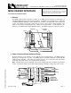
MR50 READER INTERFACE
Installation and Specifications:
1. General:
The MR50 reader interface provides a solution to the OEM system integrator for interfacing to a
TTL/Wiegand/RS-485 type reader and door hardware. The MR50 can accept data from a reader with
clock/data, Wiegand signaling or 2-wire RS-485, also provides a tri-stated LED control and buzzer
control. Two Form-C contact relay outputs may be used for strike control or alarm signaling. Two
inputs are provided for monitoring the door contact and exit push button. Communication to the
interface is accomplished via a 2-wire RS-485 interface. The MR50 requires 12 to 24 Vdc for power.
2. Power, Reader and Door Hardware Wiring:
All interconnections to the interface are via quick-disconnect terminal blocks. The MR50 requires
filtered 12 to 24 Vdc±10% for power. The MR50 supports clock/data, Wiegand or 2-wire RS-485
reader interface signaling. Two inputs are typically used for door contact and exit push button
monitoring. End of line resistors are required for line supervision.
Note: The input power is passed through to the reader terminal strip and is available for powering a
reader. Care must be taken to insure that the input voltage is within the voltage range of the reader.
1
2
3
4
5
6
7
8
J2
TB1
GND
J3
J5
TR-
TR+
VO
D0
DAT
GND
D1
LED
CLK
BZR
TB4
J4
B A
U1
J6
TB3
TB2
K2
K1
I1
I1
I2
I2
GND
VIN
C
NC
NO
C
NO
NC
K2K1
2.35 [59.7]
2.75 [69.9]
3.85 [97.8]
4.25 [108]
TAMPER INPUT, NORMALLY CLOSED
STATUS LEDs
0.20 [5.1]
0.20 [5.1]
Ø0.156 [Ø4.0]
4 PLACES
1K,1%
1K,1%
1K,1%
1K,1%
NC
NO
EXIT REQUEST
NORMALLY OPEN
DOOR CONTACT
NORMALLY CLOSED
NORMALLY CLOSED
COMMON
NORMALLY OPEN
NORMALLY OPEN
NORMALLY CLOSED
COMMON
+12 to 24 Vdc INPUT VOLTAGE
INPUT VOLTAGE RETURN
STRIKE RELAY (K1)
GROUND
BUZZER
LED
DATA1/CLOCK/TR+
DATA0/DATA/TR-
READER POWER
RS-485
INTERFACE
READER
TAMPER, NC
TB4
GND
CLK
LED
D1
DAT
D0
VO
TR+
TR-
GND
BZR
TB1
I1
I2
I1
I2
GND
C
VIN
NO
NC
C
NO
NC
K1 K2
TB3
TB2
8
2
1
5
4
3
7
6
J4
J2
J3
AUX. RELAY (K2)
K1
K2
TR-
GROUND
TR+
I2
I1
SIO COMM.