
Manual
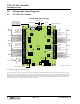
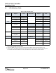
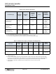
Table Of Contents

NXT 2-D/4-D Controller
Installation Guide
Page 2 of 6 P/N: 01997-001 Rev. I
1.2 LED Definitions Table
Table 1: NXT Controller LEDs
a
a. PCBs at revision F or greater have the RS-485 Bus Over Current LEDs t, u, v, and w. PCB revisions earlier
than revision F do NOT have these LEDs.
Ethernet
Comm
Purpose LED Relay State Purpose LED
10/100 a (D21) Relay 1 active n (D3)
Link b (D22) Relay 2 active o (D8)
Activity c (D33) Relay 3 active p (D13)
Utility Purpose LED
Relay 4 active q (D18)
Standard FW
Config Reset
d (D48)
Power Purpose LED
Host Channel Active e (D49) indicator r (D26)
Firmware Upgrade f (D50)
Event Channel Active g (D51)
Thermal Fuse
b
b. If LED s is green, the power wires are reversed; if LED s is red, the unit is drawing too much current.
Purpose LED
unused h (D52) indicator s (D23)
Mercury FW
Config Reset
i (D53)
RS-485 Bus Purpose LED
RS-485 Bus
c
c. If LED t, u, v, or w is red, that individual bus is drawing too much current and the bus is shut down to protect
the controller. When this condition is corrected, the LED will turn off and the bus will be activated.
Purpose LED
Bus 1 Tx j (D1) Bus 1 Over Current t (D54)
Bus 2 Tx k (D6) Bus 2 Over Current u (D55)
Bus 3 Tx l (D11) Bus 3 Over Current v (D56)
Bus 4 Tx m (D16) Bus 4 Over Current w (D57)