
Owner's manual


NXT Reader Interface Module
Installation Guide
Page 1 of 5 P/N: 02501-001 Rev. L
1.0 Wiring and Layout Diagrams
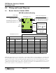
1.1 Reader Interface Module (RIM)
NOTE: This equipment has been tested and found to comply with the limits for a Class A digital device, pursuant to Part
15 of the FCC Rules. These limits are designed to provide reasonable protection against harmful interference when the
equipment is operated in a commercial environment. This equipment generates, uses, and can radiate radio frequency
energy and, if not installed and used in accordance with the instruction manual, may cause harmful interference to radio
communications. Operation of this equipment in a residential area is likely to cause harmful interference in which case
the user will be required to correct the interference at his own expense.
P/N: 02501-002 Rev. J
D10 - 12VDC
Reader Power
Selected
SW2
SW1
J2
1 2
3
4
5 6 7 8
NXT-RM Installation Drawing
Reader LED Configuration
Step
Switch
Select
Switch
12VDC
5VDC
J2 Jumper Settings
for Reader Power
Keri MS Reader - D4
Wiegand Reader - D5
NXT-6RK Keypad Reader - D6
Wiegand Combo Reader - D7
Reader Type
D1 - Single-line, three-color LED
D2 - Dual-line LED - Keri default
D3 - Single-line, two-color LED
RS-485 Comm - D8
1
2
3
4
5
6
7
8
Antenna
Beeper
Red LED
Green LED
+ 12 VDC
Ground
n/a
n/a
Blue
Green
White
Brown
Red
Black & Shield
n/a
n/a
n/a
Beeper
LED
n/a
+ 12 VDC
Ground
Data0
Data1
n/a
Blue
Brown
n/a
Red
Black & Shield
Green
White
n/a
Beeper
Red LED
Green LED
+ 12 VDC
Ground
Data0
Data1
n/a
Blue
Brown
Orange
Red
Black & Shield
Green
White
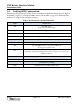
Single-Line LED Dual-Line LEDKeri MS Reader
Wiegand Reader
Connection Wire Color
* Farpointe
Wire Color
* Farpointe
Wire Color
ConnectionConnectionPin #
* For other Wiegand reader types, please refer to the reader manufacturer’s color code.