
Owner's manual


NXT Reader Interface Module
Installation Guide
Page 4 of 5 P/N: 02501-001 Rev. L
3.4 Verifying RIM Configuration
The corresponding reader type and line control mode LEDs are illuminated during operation. Refer to
the Drawing on page 1 for switch and LED locations, and the Table on page 2 for switch and LED
definitions to confirm your configuration settings.
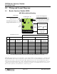
Table 2: Reader Interface Module LED Guide
LED Reader Type
D4 Keri MS Series
Keri factory default setting
D5 Wiegand
D6 Keri NXT-6RK Keypad
D7 Wiegand Reader/Keypad Combo
LED Control
D1 single wire LED control – red, green, amber, off
D2 two wire LED control – red, green, amber, off
Keri factory default setting
D3
a
a. Table is valid for RIM Firmware v03.01.06 and later. Please upgrade your firmware as necessary.
single wire LED control – red, green, off
standard setting for Wiegand Readers using a single wire to drive the
LED (no amber)
Communication Active
D8 RS-485 Bus
J2 Reader Power Setting
D10 lit when set for 12 VDC reader power