
Quick Start User guide

SB-293 Satellite Board
1530 Old Oakland Road, Suite 100 01837-003 Rev. 2.3
San Jose, CA 95112 USA
(800) 260-5265 (408) 451-2520 FAX (408) 441-0309
Web: http://www.kerisys.com E-mail: sales@kerisys.com Page 1 of 16
SB-293Quick Start Guide
This quick start guide is made up of a specification sheet, basic installation drawings and information, and short
descriptions of key terms and concepts. For comprehensive information regarding the SB-293 Satellite Board, please
refer to the Technical Reference Manual (P/N 01836-004).
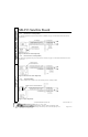
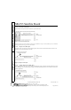
1.0 Specifications
Unit Dimensions
• PXL-250 controller PCB with an SB-293 Satellite Board
- 7.25 inches high by 6.00 inches wide by 1.75 inches deep, including wiring connectors
- (18.45 cm by 15.25 cm by 4.45 cm)
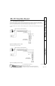
• PXL-250 controller PCB with an SB-293 Satellite Board and an LCD-1 Alpha/Numeric Display
- 8.10 inches high by 6.00 inches wide by 1.75 inches deep, including wiring connectors
- (20.60 cm by 15.25 cm by 4.45 cm)
•Enclosure
- 9.70 inches high by 8.20 inches wide by 2.60 inches deep
- (24.65 cm by 20.85 cm by 6.60 cm)
Operating Temperature/Humidity Range
• 0°F to 140°F (-18°C to 60°C)
• 0% to 90% Relative Humidity, non-condensing
Controller with Satellite Board Power Requirements
• 12 VDC @ 1 Amp
Current Draw
• maximum current draw 270 mA for a controller plus reader current draw (refer to Table 1 for Reader current draw)
• 120 mA max for a PXL-250 Controller
• 150 mA max for an SB-293 Satellite Board
Output Relay Contact Rating
• 1 Amp @ 24 VDC
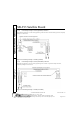
Input Device Configuration
• Door Sense normally closed
• Request to Exit normally open
• Global Unlock normally open, or
Auxiliary RTE A-Door normally open
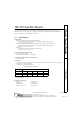
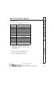
Table 1: Reader Current Draw
Reader Type
MS-3000 MS-4000 MS-5000 MS-7000 MS-9000
Current Draw
50 mA 50 mA 100 mA 200 mA 200 mA