
Quick Start User guide

SB-293 Satellite Board
1530 Old Oakland Road, Suite 100 01837-003 Rev. 2.3
San Jose, CA 95112 USA
(800) 260-5265 (408) 451-2520 FAX (408) 441-0309
Web: http://www.kerisys.com E-mail: sales@kerisys.com Page 2 of 16
Quick Start GuideSB-293
2.0 Cable Requirements
• two conductor, stranded, AWG 22 or a larger gauge for all input/output connections
NOTE: The Lock Output relay may require a heavier gauge of wire depending upon the current demands of the lock and
the length of the lock wiring run.
3.0 When Installing Satellite Boards
DO
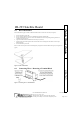
• route cables in accessible areas for ease of maintenance
• add transient suppression across electric devices attached to a satellite board output
• use an isolation relay (Keri Systems P/N IRP-1) if attaching to a parking gate, a turnstile, or any application using a
large electric motor
• for a single door application, install the door's reader to the TB-5, "A" reader connection on the controller
• for a two door application, install the primary door's reader to the TB-5, "A" reader connection on the controller
and install the secondary door's reader to the TB-6, "B" reader connection on the controller
DO NOT
• stretch or over-tension cables
• route cables over sharp objects
• let cables or wires get tangled
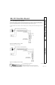
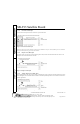
4.0 Jumper Setting
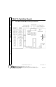
JP12 - Configures the Satellite Board (see Figure 1)
• Jumper across JP12, pins 1 and 2, configures the Satellite board for general purpose inputs and outputs.
• NO jumper across JP12 configures the Satellite board for second door control with additional inputs and outputs.
When the Satellite board is configured for second door control, the primary door must be connected to the "A"
reader (TB-5 on the PXL-250 controller board) and the secondary door must be connected to the "B" reader (TB-6
on the controller board).
Figure 1: Setting JP12