KERN & Sohn GmbH Ziegelei 1 D-72336 Balingen E-Mail: info@kern-sohn.com Phone: +49-[0]7433- 9933-0 Fax: +49-[0]7433-9933-149 Internet: www.kern-sohn.com Installation instructions weighing bridge (≥600 kg) KERN KFP V40 Version 1.
GB KERN KFP V40 Version 1.0 09/2011 Installation instructions weighing bridge Contents 1 General ........................................................................................................... 3 2 Technical data ................................................................................................ 3 3 Basic instructions.......................................................................................... 3 3.1 Documentation .................................................
1 General These installation instructions contain all data necessary for placing and commissioning the weighing bridge KERN KFP 1500V40M. 2 Technical data Model KFP 1500V40M Weighing range Max kg 1500 g Verificati on value e g Minimum load Min kg 500 500 10 Readabil ity d Preload additive kg Cable length approx. m Net weight approx. kg 250 3 175 3 Basic instructions 3.
3.4 Warranty Warranty claims shall be voided in case • Our conditions in the operation manual are ignored • The appliance is used outside the described uses • Structural changes of the device • Mechanical damage and damage caused by media, liquids • Natural wear and tear • The appliance is improperly set up or incorrectly electrically connected • Overload of the measuring system 3.
4 Basic Safety Precautions 4.1 Pay attention to the instructions in the Operation Manual Carefully read this operation manual before setup and commissioning, even if you are already familiar with KERN balances. 4.2 Personnel training The appliance may only be operated and maintained by trained personnel. The installation of a display unit must only be carried out by a well acquainted specialist with the workings of weighing balances. 5 Transport and storage 5.
Unpacking, Setup and Commissioning 6.1 Installation Site, Location of Use The weighing bridges are designed in a way that reliable weighing results are achieved in common conditions of use. You will work accurately and fast, if you select the right location for your weighing system. On the installation site observe the following: • Place the weighing bridge on a firm, level surface.
6.2 Unpacking, Scope of delivery + CAUTION + Danger for the back! The weighing bridge is relatively heavy. Always use a suitable lifting device to lift it out of the packaging or to transport it to the required installation site. Do not step under the suspended load, risk of injury! Scope of delivery: • Weighing bridge with assembled connection cable • 4 weighing cell feet • Operating instructions Ensure that the contents of package is complete.
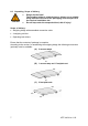
6.3 Assembly, levelling Accurate weighing results require a weighing bridge with perfect horizontal alignment. During initial installation and after each change of work area it is necessary to level the weighing bridge. Placing the weighing bridge: 1. Prior to the final placing, install the four weighing cell feet. 2. Place the weighing bridge equally on the installation site and check if it is in an even position and all four feet are in contact with the floor.
6.4 Connecting a display unit Attention Put the connecting cable to the display unit in a manner that it is protected against damage.
7.1 Operation limits • The weighing bridges are designed extremely robust. However the load limits according to the following table should not be exceeded! • Depending on the type of load receptacle, the static carrying capacity, i.e. the maximum admissible load is: Weighing ranges 1500kg With centrical load 4500kg With side stress 3000kg With one-sided loading 1500kg With single-wheel load 800kg 7.
8 Service, maintenance, disposal Before any maintenance, cleaning and repair work disconnect the appliance from the operating voltage. 8.1 Daily check Ö Ensure that all four feet are in contact with the floor. Ö Ensure that the connecting cable to the display unit and the network connection cable of the display unit are not damaged. Ö Ensure that the balance is free from dirt, especially under the edges of the balance. 8.2 Cleaning Ö Remove regularly corrosive substances. Ö Keep IP protection.
8.5 Instant help In case of an error in the program process, briefly turn off the balance and disconnect from power supply. The weighing process must then be restarted from the beginning. Help: Fault The displayed weight is permanently changing Possible cause • Draught/air movement • Floor vibrations • Weighing plate has contact with other objects.
9 Service documentation 9.1 • This chapter is only intended for a balance specialist! • The weighing bridges are carried out in DMS sensor technology, at every corner a DMS weighing cell is installed. • The analogue-digital transformation occurs in the display unit. Also all the balance and country-specific data are stored there.
9.2 Check and adjustment of the corner load Check of the corner load: • Place the test weights in the centre of the load plate and tare. • The balance displays -0-. • Place the test weights successively on all four corners. Now the deviations are displayed with sign, write down the values. If there are deviations out of the tolerances (see chap. 9.1), an adjustment will be necessary.
10 Preload, Deadload and Overload settings Kern model max. Preload* (kg) Deadload** (kg) * = additive preload **= already applied preload 160kg KFP 1500V40M Platform type KFP 1500V40M 15 0 Platform dimension (mm) 1500x1250x90 Loadcell Type SQB TC No.