KERN & Sohn GmbH Ziegelei 1 D-72336 Balingen E-Mail: info@kern-sohn.com Phone: +49-[0]7433- 9933-0 Fax: +49-[0]7433-9933-149 Internet: www.kern-sohn.com Installation instructions weighing bridge (600 kg) KERN KFP V20 Version 1.
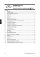
GB KERN KFP V20 Version 1.3 10/2013 Installation instructions weighing bridge (600 kg) Contents 1 2 3 General ........................................................................................................... 3 Technical data ................................................................................................ 3 Basic Information (General) .......................................................................... 4 3.1 3.2 3.3 3.4 3.5 Documentation .................................
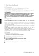
1 General These installation instruction contain all data necessary for placing and commissioning the following weighing bridges: KERN KFP 600V20SM KERN KFP 600V20M KERN KFP 1500V20SM KERN KFP 1500V20M KERN KFP 3000V20M KERN KFP 3000V20LM KERN KFP 6000V20M 2 Technical data Model Weighing range Max Readabil ity d Verificati on value e Minimum load Min Preload additive Cable length approx. Net weight approx.
3 Basic Information (General) 3.1 Documentation These installation instruction contain all data necessary for placing and commissioning the weighing bridges KERN KFP V20. In combination with a display unit, described below as weighing system, for operation configuration, please refer to the operating instructions of the display unit. 3.2 Proper use The balance you purchased is intended to determine the weighing value of material to be weighed. It is intended to be used as a “non-automatic balcance”, i.e.
3.5 Monitoring of Test Resources In the framework of quality assurance the measuring-related properties of the weighing system and, if applicable, the testing weight, must be checked regularly. The responsible user must define a suitable interval as well as type and scope of this test. Information is available on KERN’s home page (www.kern-sohn.com with regard to the monitoring of weighing system test substances and the test weights required for this.
Unpacking, Setup and Commissioning 6.1 Installation Site, Location of Use The weighing bridges are designed in a way that reliable weighing results are achieved in common conditions of use. You will work accurately and fast, if you select the right location for your weighing system. On the installation site observe the following: Place the weighing system on a firm, level surface.
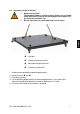
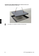
6.2 Unpacking, Scope of delivery + CAUTION + Danger for the back! The weighing bridge is relatively heavy. Always use a suitable lifting device to lift it out of the packaging or to transport it to the required installation site. Do not step under the suspended load, risk of injury! Eye bolts Covering weighing cell feet Adjustable weighing cell feet Covering Junction-Box 1. 2. 3. 4. Remove outer packaging and packaging material. Remove covers and .
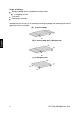
Scope of delivery: Weighing bridge with assembled connection cable 4 weighing cell feet 2 eye bolts Operating instructions According to the version, for assembling the weighing bridge the following accessories (optional) must be available: (A) 2 access ramps or (B) 1 access ramp and 1 foot plate set or (C) 2 foot plate sets 8 KFP V20_600-6000-IA-e-1313
6.3 Assembly, levelling Accurate weighing results require a weighing bridge with perfect horizontal alignment. During initial installation and after each change of work area it is necessary to level the weighing bridge. Placing the weighing bridge: 1. Prior to the final placing, install the four weighing cell feet. 2. Place the weighing bridge equally on the installation site and check if it is in an even position and all four feet are in contact with the floor.
Installation of the weighing bridge in pits for barrier-free access Order the suitable pit frame as accessory. Assembly see installation instructions of the pit frame.
6.4 Connecting a display unit Attention Put the connecting cable to the display unit in a manner that it is protected against damage.
7.1 Operation limits The weighing bridges are designed extremely robust. However the load limits according to the following table should not be exceeded! Depending on the type of load receptacle, the static carrying capacity, i.e.
8 Service, maintenance, disposal Before any maintenance, cleaning and repair work disconnect the appliance from the operating voltage. 8.1 Daily check Ensure that all four feet are in contact with the floor. Ensure that the connecting cable to the display unit and the network connection cable of the display unit are not damaged. Ensure that the balance is free from dirt, especially under the edges of the balance. 8.2 Cleaning Remove regularly corrosive substances. Keep IP protection.
8.5 Instant help In case of an error in the program process, briefly turn off the balance and disconnect from power supply. The weighing process must then be restarted from the beginning. Help: Fault The displayed weight is permanently changing Possible cause Draught/air movement Floor vibrations Weighing plate has contact with other objects.
9 Service documentation This chapter is only intended for a balance specialist! The weighing bridges are carried out in DMS sensor technology, at every corner a DMS weighing cell is installed. The analogue-digital transformation occurs in the display unit. Also all the balance and country-specific data are stored there. 9.
Verification data and tolerances as per OIML 600kg 0,4 [g] 0,3 0,2 0,1 0 [kg] -0,1 -0,2 -0,3 -0,4 0 100 200 300 400 500 600 1500kg 1 [g] 0,75 0,5 0,25 0 [kg] -0,25 -0,5 -0,75 -1 0 500 1000 1500 3000kg 2 [g] 1,5 1 0,5 0 [kg] -0,5 -1 -1,5 -2 0 1000 2000 3000 6000kg 16 KFP V20_600-6000-IA-e-1313
9.2 Check and adjustment of the corner load Check of the corner load: Place the test weights in the centre of the load plate and tare. The balance displays -0-. Place the test weights successively on all four corners. Now the deviations are displayed with sign, write down the values. If there are deviations out of the tolerances (see chap. 9.1), an adjustment will be necessary.
Adjustment on the analogue print Adjustment of weighing cell J2 takes place at the potentiometer VR1 and VR2. Adjustment of weighing cell J3 takes place at the potentiometer VR3 and VR4. Adjustment of weighing cell J4 takes place at the potentiometer VR5 and VR6. Adjustment of weighing cell J5 takes place at the potentiometer VR7 and VR8. Increase the value turning to the right, reduce the value turning to the left.
10 Preload, Deadload and Overload settings max. Preload* (kg) Kern model * = additional initial load KFP 600V20SM KFP 600V20M KFP 1500V20SM KFP 1500V20M KFP 3000V20M KFP 3000V20LM KFP 6000V20M Platform type Deadload** (kg) **= already applied preload 0 0 0 0 0 0 0 Platform dimension (mm) 100kg 160kg 100kg 160kg 160kg 160kg 160kg Loadcell Type TC No.