KERN & Sohn GmbH Ziegelei 1 D-72336 Balingen E-Mail: info@kern-sohn.com Phone: +49-[0]7433- 9933-0 Fax: +49-[0]7433-9933-149 Internet: www.kern-sohn.com Operating and Installation Instructions Display devices KERN KFB/KFN-TM Version 2.
GB KERN KFB/KFN-TM Version 2.3 07/2013 Operating and installation instructions Display units Contents 1 Technical data ................................................................................................ 4 2 Appliance overview ....................................................................................... 5 2.1 2.1.1 Keyboard overview .....................................................................................................................
7 Operation ...................................................................................................... 24 7.1 Start-up ..................................................................................................................................... 24 7.2 Switching Off ............................................................................................................................ 24 7.3 Zeroing ...............................................................................
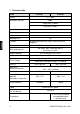
1 Technical data KERN KFB-TM KFN-TM Display 5 ½ - digit Resolution (verified) 6000 Single (Max.) 6.000 e Dual (Max.) 3.000 e Resolution (non-verified) 30.000 Weighing ranges 2 Divisions 1,2,5,…10n Weighing Units Functions Display DMS weighing cells Range calibration kg Weighing with tolerance range, Totalizing, Animal weighing LCD 52 mm digits with back lighting 80-100 Ω. Max. 4 item per 350 Ω; Sensitivity 2-3 mV/V We recommend ≥ 50 % max.
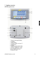
2 Appliance overview KFB-TM: Synthetic finish 1. Status of rechargeable battery 2. Keyboard 3. Weight display 4. Tolerance margin, see chap. 7.7 5. Weighing unit 6. RS-232 7. Input connection load cell cable 8. Guide rail support base / stand 9. End stop support base / stand 10. Mains adapter connection 11.
KFN-TM: Stainless steel finish 1. 2. 3. 4. 5. 6. 7. 6 Status of rechargeable battery Keyboard Weight display For tolerance mark see chap. 7.
2.
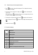
2.1.1 Numerical input via the navigation buttons Press and current setting will be displayed. The first digit will be flashing and is ready for changing. If you do not wish to change the first digit, press and the second digit will start flashing. Each time you press , the display will move to the subsequent digit, after the last digit the display will return to the first digit. To change the selected (flashing) digit, press value is displayed.
3 Basic Information (General) 3.1 Proper use The display unit acquired by you is used in combination with a weighing plate and serves to determine the weighing value of material to be weighed. It is intended to be used as a “non-automatic weighing system”, i.e. the material to be weighed is manually and carefully placed in the centre of the weighing plate. As soon as a stable weighing value is reached the weighing value can be read. 3.2 Improper Use Do not use display unit for dynamic weighings.
3.4 Monitoring of Test Resources In the framework of quality assurance the measuring-related properties of the display unit and, if applicable, the testing weight, must be checked regularly. The responsible user must define a suitable interval as well as type and scope of this test. Information is available on KERN’s home page (www.kern-sohn.com with regard to the monitoring of display units’ test substances and the test weights required for this.
6 Unpacking and placing 6.1 Installation Site, Location of Use The display units are designed in a way that reliable weighing results are achieved in common conditions of use. Precise and fast work is achieved by selecting the right place for your display unit and your weighing plate. On the installation site observe the following: • • • • • • • Place the display unit and the weighing plate on a stable, even surface.
6.4 Transportation lock (illustration example) Please note: if the display unit is used together with platform with transportation lock, this transportation lock must be released prior to use: Transport Securing 6.5 Error message As soon as an error message appears in the balance display, the balance must not more be used, e.g.
6.6 Placing Mount the display unit in a way that facilitates operation and where it is easy to see. Usage with support base (KFB-TM only) Push support base holder in guide rail [8] up to end stop [9], see chap. 2. Usage with wall mount (KFB-TM only) Use the wall mount to affix the display unit to the wall. Using with tripod (optional) An optional tripod (KERN BFS-07) is available if the display unit is to be mounted in a raised position.
6.7 Mains connection Power is supplied via the external mains adapter. The stated voltage value must be the same as the local voltage. Only use original KERN mains adapters. Using other makes requires consent by KERN. 6.8 Storage battery operation (optional) Before the first use, the battery should be charged by connecting it to the mains power supply for at least 12 hours. If the weight display shows , this is an indication that the capacity of the rechargeable battery is almost exhausted.
6.9 Adjustment As the acceleration value due to gravity is not the same at every location on earth, each display unit with connected weighing plate must be coordinated - in compliance with the underlying physical weighing principle - to the existing acceleration due to gravity at its place of location (only if the weighing system has not already been adjusted to the location in the factory).
Call up menu: 1. Switch-on balance and during the selftest press . 2. Press , , subsequently, the first menu block „PO CHK“ will be displayed. 3. Press repeatedly until „P2 mode“ will be displayed. For the KFB-TM model operate the adjustment switch. 4. Press and select the set weighing scales type by . = Single-range balance = Dual range balance = Multi-interval balance 5. Acknowledge with 6. Press repeatedly until „CAL“ will be displayed. 7. Confirm with 16 .
How to carry out an adjustment: Confirm menu setting „noLin“ by . Ensure that there are no objects on the weighing plate. Wait for stability display, then press . The currently set adjustment weight will be displayed. To change by using the navigation buttons (see chap. 2.1.1) select the desired setting, the active digit is flashing. Acknowledge with . Carefully place adjusting weight in the centre of the weighing plate. Wait for stability display, then press .
6.9.2 Non verifiable weighing systems Call up menu: 1. Switch-on balance and during the selftest press 2. Press subsequently , „PO CHK“ will be displayed. 3. Press , . the first menu block repeatedly until „P3 CAL“ will be displayed. 4. Confirm with appears. ; press 5. Acknowledge using repeatedly until „CAL“ , the current setting is displayed. Press to confirm; press to select setting. noLin = adjustment LineAr = linearization, see chap. 6.
6.10 Linearization Linearity shows the greatest deviation of a weight display on the scale to the value of the respective test weight according to plus and minus over the entire weighing range. If linearity deviation is discovered during a testing instrument control, you can improve this by means of linearization. • • • • • • 6.10.1 In balances with a resolution of > 15 000 dividing steps carrying out a linearisation is recommended.
After linearisation the balance will carry out a self-test. Remove adjusting weight during selftest, balance will return into weighing mode automatically. 6.10.2 Non-verified weighing systems Call-up menu item P3 CALCalLiner, see chap. 6.9.1 Confirm by , the password query „Pn“ will be displayed. Press , , or , , subsequently. Ensure that there are no objects on the weighing pan. Wait for stability display, then press .
6.11 Verification General introduction: According to EU directive 90/384/EEC balances must be officially verified if they are used as follows (legally controlled area): a) For commercial transactions if the price of goods is determined by weighing. b) For the production of medicines in pharmacies as well as for analyses in the medical and pharmaceutical laboratory. c) For official purpose. d) For manufacturing final packages. In cases of doubt, please contact your local trade in standard.
Notes on verified weighing systems KFB-TM: Access to conductor plate: • • • Remove seal Open display unit The application of the display unit as a weighing system able to be verified requires that the contacts of the circuit board are short-circuited with the help of a jumper [K1]. For non verifiable weighing systems remove the jumper. [K1] In verified weighing systems the menu item for adjustment, „P2 mode“ will be blocked. To disable the access lock, destroy the seal and actuate the adjustment switch.
KFN-TM: Access to conductor plate: • • • • Remove seal Open display unit The application of the display unit as a weighing system able to be verified requires that the contacts of the circuit board are short-circuited with the help of a jumper [K1]. For non verifiable weighing systems remove the jumper. To adjust, short-circuit the contacts of the circuit board, using a jumper [K2].
7 Operation 7.1 Start-up Press and the instrument will carry out a self-test. As soon as the weight display appears, the instrument will be ready to weigh. 7.2 Switching Off Press and the display will disappear. 7.3 Zeroing Resetting to zero corrects the influence of light soiling on the weighing plate. The unit is equipped with an automatic zero setting function. Therefore the unit can be reset to zero at any time as follows: To unload the weighing system Press 7.
7.5 Switch-over weighing unit (only not verifiable weighing systems) How to enable weighing units: Call-up menu item P5 Unt, see chap. 8.1 Press and the first weighing unit with the current setting will be displayed. To enable [on] / disable [off] the displayed weighing unit, press Acknowledge with . The next unit with the current setting will be displayed. To enable [off] / disable [on] the displayed weighing unit, press . Acknowledge with .
7.6 Weighing with tare Deposit weighing vessel. After successful standstill control press the button. Zero display and indicator NET appear. The weight of the container is now internally saved. Weigh the material, the net weight will be indicated. The weight of the weighing container will be displayed as a minus number after removing the weighing container.
7.7 Weighing with tolerance range You can set an upper or lower limit when weighing with tolerance range and thus ensure that the weighed load remains exactly within the set limits. During tolerance tests such as dosing, portioning and sorting the unit will indicate exceeded or undershot limits by emitting an optical or acoustic signal. Audio signal: The acoustic signal depends on the settings in menu block „BEEP“.
7.7.1 Tolerance check for target weight Settings Press Press and at the same time in weighing mode. until the display for entering the lower limit value appears. Press , the current setting will be displayed. To enter the lower limit, e. g. 1000 Kg, press the navigation keys (See chap. 2.1.1); the currently enabled digit will be flashing. Confirm input by . Press repeatedly until Press , the current setting for the upper limit will be is displayed. displayed.
Press ; weighing system is in tolerance weighing mode. From here evaluation takes place whether the goods to be weighed are within the two tolerance limits. Weighing with tolerance range Tare when using a weighing container. Put on goods to be weighed, tolerance control is started. The signal lights indicate whether the load is within the two set limits.
7.7.2 Tolerance check for target quantity Settings Press Press and at the same time in weighing mode. until the display for entering the lower limit value appears. Press , the current setting will be displayed. To enter the lower limit, e. g. 75 items, press the navigation buttons (see chap. 2.1.1); the currently enabled digit will be flashing. Confirm input by . Press repeatedly until Press , the current setting for the upper limit will be is displayed. displayed.
Press ; weighing system is in tolerance weighing mode. From here evaluation takes place whether the goods to be weighed are within the two tolerance limits. Weighing with tolerance range Set item weight, see chap. 7.10. Tare when using a weighing container. Put on goods to be weighed, tolerance control is started. The signal lights indicate whether the load is within the two set limits.
7.8 Manual totalizing With this function the individual weighing values are added into the summation memory by pressing • • and edited, when an optional printer is connected. Menu setting: „P1 COM“ or „P2 COM“ „MODE“ „PR2““, see chap. 8 The totalizing function is not active when the weight is under 20d. Add up: Place weighing goods A. Wait until the stability display STABLE appears, then press will be saved and printed if an optional printer is connected. .
Delete weighing data: Press and at the same time The data in the summation memory are deleted.
7.9 Automatic adding-up With this function the individual weighing values are automatically added into the summation memory when the balance is unloaded without pressing when an optional printer is connected. • and edited, Menu settings: „P1 COM“ or „P2 COM „MODE“ „AUTO““, see chap. 8 Der Indikator AUTO wird angezeigt. Add up: Place weighing goods A. After the standstill control sounds a signal tone. The weighing value will be added to the summation memory and printed. Remove the weighed good.
7.10 Parts counting Before the balance can count parts, it must know the average part weight (i.e. reference). Proceed by putting on a certain number of the parts to be counted. The balance determines the total weight and divides it by the number of parts, the socalled reference quantity. Counting is then carried out on the basis of the calculated average piece weight. As a rule: The higher the reference quantity the higher the counting exactness.
7.11 Animal weighing The animal weighing function is suitable for weighing restless loads. The weighing system will display a mean value derived from several weighing results. The animal weighing program can be enabled by either calling up menu block „P3 OTH“ or „P4 OTH“ „ANM“ „ON“ (See chap. 8) or faster via key combination. The indicator shows HOLD as long as the animal weighing function remains enabled. Place the load on the weighing system and wait until the scale is steady.
7.12 Lock keyboard To enable/disable the keyboard lock go to menu item „P3 OTH“ or „P4 OTH“ „LOCK“, see chap.8. Whilst the function is enabled the keyboard will self-lock after no key has been pressed for 10 minutes. „K-LCK“ will be displayed as soon as a key is pressed. To disable the lock, press , and hold plus (2 s) until „U LCK“ appears. 7.13 Display background illumination Keep pressed (3s) until „setbl“ appears. Press again, the current setting will be displayed.
7.14 Automatic switch-off function „AUTO OFF“ The unit is automatically switched off within the preset time when the display unit or the weighing bridge are not operated. Keep pressed (3s) until „setbl“ appears. Press to call up AUTO OFF-function Press , the current setting will be displayed. Use to select the desired setting. of 0 AUTO OFF - of 3 Weighing system will be turned off after 3 min. of 5 Weighing system will be turned off after 5 min.
8 Menu The application of the display unit as a verified weighing system requires that you short-circuit the two contacts [K1] of the circuit board, using a jumper. To that effect, a menu for verified weighing systems is available. For menu layout see chap. 8.2. There is no jumper for weighing systems that cannot be verified. To that effect, a menu is available for weighing systems that cannot be verified, Menu layout see chap. 8.
8.1 Overview non verifiable weighing systems (contacts of circuit board [K1] not short-circuited) Menu block Main menu PO CHK Weighing with tolerance range, see chap. 7.7 Menu item Submenu nEt H Available settings / explanation Upper limit value „Tolerance check weighing“, input see chap. 7.7.1 nEt LO Lower limit value „Tolerance check weighing“, input see chap. 7.7.1 PCS H Upper limit value „Tolerance check counting“, input see chap. 7.7.
AUTO* For automatic add-up see chap. 7.9. This function is used to issue and add individual weighing values automatically to the summation memory on unloading of weighing scale. BAUD Pr PTYPE Lab Prt LAnG P3 CAL Configuration data see chap. 12.4 COUNT DECI DUAL CAL GrA P4 OTH LOCK ANM KFB/KFN-TM-BA_IA-e-1323 ASK For remote control commands, see chap. 10.
P5 Unt Switch-over weighing unit, see chap. 7.5 kg g lb oz tJ HJ P6 xcl on* off on off* on off* on off* on off on off Not documented P7 rst Use P8 uwb to reset balance settings to factory default. Not documented Factory settings are marked by *.
8.2 Overview verified weighing systems (contacts of circuit board [K1] short-circuited by means of jumper) In verified weighing systems the access to „P2 mode and „P4 tAr“ is locked. KERN KFB-TM: To disable the access lock, destroy the seal and actuate the adjustment switch. Position of the adjustment switch see chap. 6.11. KERN KFN-TM: In order to unlock the access, the seal must be destroyed and both contacts of the printed circuit board [K2] must be short-circuited by a jumper, see chap. 6.11.
For remote control commands, see chap. 10.4 Not documented wireless Available Baudrate: 600, 1200, 2400, 4800, 9600 7E1 7 bits, even parity 7o1 7 bits, odd parity 8n1 8 bits, no parity tPUP Standard printer setting LP50 Not documented Lab x Details see following table 1 Prt x Eng* Standard setting English Chn ASK baud Pr PtYPE Lab Prt Lang P2 mode SiGr Single-range balance COUNT DECI Div.
dUAL 2 P3 OTH Multi-interval balance Weighing scales with one weighing range subdivided into partial weighing ranges, each providing a different scale interval. The scale interval depends on the applied load and is automatically changed during loading and unloading. COUNT Display internal resolution DECI Position of the decimal dot Readability [d] / verification value [e] div 1 1. weighing range div. Readability [d] / verification value [e] div 2 2. weighing range Weighing scale capacity [max] CAP 1 1.
9 Service, maintenance, disposal 9.1 Clean • Before cleaning, disconnect the appliance from the operating voltage. • Do not use aggressive detergents (solvents or similar). 9.2 Service, maintenance The appliance may only be opened by trained service technicians who are authorized by KERN. Before opening, disconnect from power supply. 9.3 Disposal Disposal of packaging and appliance must be carried out by operator according to valid national or regional law of the location where the appliance is used. 9.
Err 10 Communication error • No data Err 15 Gravitation error • Range 0.9 ~ 1.0 Err 17 Taring range exceeded • Reduce load Adjustment error • Repeat adjustment. Printer error • Check communication parameters Battery very low • Recharge battery Fai l h / Fai l l Err P Ba lo / Lo ba Should other error messages occur, switch balance off and then on again. If the error message remains inform manufacturer.
10 Data output RS 232C You can print weighing data automatically via the RS 232C interface or manually by pressing via the interface according to the setting in the menu. This data exchange is asynchronous using ASCII - Code. The following conditions must be met to provide successful communication between the weighing system and the printer. • Use a suitable cable to connect the display unit to the interface of the printer. Faultless operation requires an adequate KERN interface cable.
Symbols: ST Stable value US Instable value GS / GW Gross weight NT Net weight TW Tare weight NO Number weighing processes TOTAL Total of all individual weighings Space line Space line • Counting **************************** PCS 100 **************************** 10.3 Output log (continuous output) • Weighing HEADER1: ST=STABLE, US=UNSTABLE HEADER2: NT=NET, GS=GROSS 10.
11 Instant help In case of an error in the program process, briefly turn off the display unit and disconnect from power supply. The weighing process must then be restarted from the beginning. Help: Fault The displayed weight does not glow. Possible cause • The display unit is not switched on. • • Mains power supply interrupted (mains cable defective). Power supply interrupted. (Rechargeable) batteries are inserted incorrectly or empty No (rechargeable) batteries inserted.
12 Installing display unit / weighing bridge • Installation / configuration of a weighing system must be carried out by a well acquainted specialist with the workings of weighing balances. 12.1 Technical data Supply voltage: 5 V/150mA Max. signal voltage 0-10 mV Zeroing range 0-2 mV Sensitivity 2-3 mV/V Resistance parameter 80 - 100 Ω, max 4 items per 350 Ω load cell 12.
12.3 How to connect the platform Disconnect the display unit from the power supply. Solder the individual leads of the load cell cable onto the circuit board. See diagrams below.
12.4 Configure display unit 12.4.1 Verified weighing systems (contacts of circuit board [K1] short-circuited by means of jumper) For menu overview see chap. 8.2. In verified weighing systems the menu item for calibration „P2 mode“ is blocked. KERN KFB-TM: To disable the access lock, destroy the seal and actuate the adjustment switch. Position of the adjustment switch see chap. 6.
Example single range scales (d = 10 g, max. 30 kg) Confirm selected weighing scales type by pressing ; the first menu item „COUNT“ will be shown. 1. Display internal resolution Press , the internal resolution will be shown. Return to menu by Press 2. . to select the next menu item. Position decimal point Press , the currently set position of the decimal dot is displayed. Press to select the desired setting. Options 0, 0.0, 0.00, 0.000, 0.0000. Confirm input by Press 3. .
4. Capacity Press , the current setting will be displayed. Using the navigation buttons (see chap. 2.1.1) select the desired setting, the active digit is flashing. Confirm input by Press . to select the next menu item. 5. Adjustment / linearization Adjustment or linearization is required after entering configuration data. For carrying out adjustment see chap. 6.9.1/step 6 or chap. 6.10.
Example dual range scales (d = 2 / 5 g, max. 6 / 15 kg) Confirm selected weighing scales type by ; the first menu item „COUNT“ will be shown. 1. Display internal resolution Press , the internal resolution will be shown. Return to menu by Press 2. . to select the next menu item. Position decimal point Press , the currently set position of the decimal dot is displayed. Use to select the desired setting. Options 0, 0.0, 0.00, 0.000, 0.0000. Confirm input by Press 56 .
3. Readability Press , the display used to enter readability/verification value for first weighing range will appear. Press , the current setting will be displayed. Select desired setting with and acknowledge by . Press to enter the next menu item for readability/verification value for second weighing range. Press and current setting will be displayed. Select desired setting with and acknowledge by Press , the unit will return to the menu Press to select the next menu item.
4. Capacity Press and the display for entering the capacity for the first weighing range will appear. Press and current setting will be displayed. Select desired setting with and acknowledge by . Press to select the next menu item used to enter the capacity for the second weighing range. Press and current setting will be displayed. Select desired setting with Press Use and acknowledge by . , the unit will return to the menu toselect next menu item. 5.
12.4.2 Non verifiable weighing systems (contacts of circuit board [K1] not short-circuited ) + For menu overview see chap. 8.1. Call up menu Switch-on balance and during the selftest press . Press , , subsequently , the first menu block „PO CHK“ will be displayed. Press repeatedly until „CAL“ will be displayed. Press , the first menu item „COUNT“ will be displayed. Navigation in the menu With help of , the individual menu items can be selected one after the other.
Parameter selection 1. Display internal resolution Press , the internal resolution will be shown. Return to menu by Use 2. . to select another menu item. Position decimal point Press , the currently set position of the decimal dot is displayed. To make changes using the navigation keys (See chap. 2.1.1), select the desired setting. Options 0, 0.0, 0.00, 0.000, 0.0000. Confirm input by Use 3. . to select another menu item.
Select desired setting with and acknowledge by . Press , the display for entering capacity will appear (at dual range balance for the first range). Press , the current setting will be shown (such as max. = 2000kg). Using the navigation buttons (see chap. 2.1.1) select the desired setting, the active digit is flashing. Acknowledge with . In a single-range balance the entry of capacity / readability is finished.
Press , the display for entering the readability of the second weighing range will appear. Press , the current setting will be displayed. Select desired setting with and acknowledge by Press , the unit will return to the menu Press to call next menu item. . 4. Adjustment or linearisation Adjustment or linearisation is required after entering configuration data. For carrying out adjustment see chap. 6.9.2/step 4 or chap. 6.10.
13 Declaration of Conformity / Test Certificate KERN & Sohn GmbH D-72322 BalingenFrommern Postbox 4052 E-Mail: info@kernsohn.de Phone: 0049-[0]7433- 99330 Fax: 0049-[0]7433-9933-149 Internet: www.kern-sohn.
TEST CERTIFICATE No. DK0199-R76-11.04 Instrument type KFN-TM / KFB-TM Test item device Non-automatic Weighing Indicator Issued by DELTA Danish Electronics, Light & Acoustics EU - Notified Body No. 0199 In accordance with Paragraph 8.1 of the European Standard on metrological aspects of non-automatic weighing instruments EN 45501:1992. Fractional factor (pi) 0.5 (refer to 3.5.4 of the standard).
Annex page 1 of 7 Annex to Test Certificate No. DK0199-R76-11.04 1. Name and type of instrument The indicators KFN-TM / KFB-TM are a family of weighing indicators suitable to be incorporated in non-automatic weighing instruments, class III or class IIII, with single-interval, multi-interval or multi-range. 2. Description of the construction and function 2.
Annex page 2 of 7 Annex to Test Certificate No. DK0199-R76-11.04 • Indication of zero • Semi-automatic subtractive tare • Acting upon significant fault • Weighing unstable samples • Real time clock (optional) 3. Technical data 3.
Annex page 3 of 7 Annex to Test Certificate No. DK0199-R76-11.04 4. Interfaces 4.1 Load cell interface Refer to section 3.1.1. Any load cell(s) can be used for instruments under this certificate provided the following conditions are met: • There is a respective test certificate (EN 45501) or an OIML Certificate of Conformity (R60) issued for the load cell by a Notified Body responsible for type examination under the Directive 2009/23/EC.
Annex page 4 of 7 Annex to Test Certificate No. DK0199-R76-11.04 6. Location of seals and inscriptions Seals shall bear the verification mark of a notified body or alternative mark of the manufacturer according to ANNEX II, section 2.3 of the Directive 2009/23/EC. The seals shall be placed so that the enclosure can not be opened. Location of CE mark of conformity: The CE mark of conformity is placed on the overlay on the rear side of the device. Inscription on the overlay: Type, accuracy class, Temp.
Annex page 5 of 7 Annex to Test Certificate No. DK0199-R76-11.04 8. Documentation Contents of the technical documentation held by the notified body: 8.1 Product specification • Manuals and descriptions • Drawings • Etc. 8.2 Examination report OIML R76 report no. DANAK-1910568, DANAK-1910388 and NMi 709226. 8.3 Test results Report no. DANAK-1910568, DANAK-1910388 and NMi 709226.
Annex page 6 of 7 Annex to Test Certificate No. DK0199-R76-11.04 Pictures After remove the label, you will find VOID on housing, or a self destroyable sticker/seal shall be used. 9. Figure 1 Sealing of KFN-TM.
Annex page 7 of 7 Annex to Test Certificate No. DK0199-R76-11.04 Figure 2 Sealing of KFB-TM.