
Installation Manual


3. INSTALLATION OF THE BOILER
Read Chapter 2 - Boiler Location and decide upon the position of the boiler.
Installation of the boiler is straightforward but consideration must be given to access to allow flue
and air pipes to be pushed through walls and ceilings. The order in which the components are
installed will depend upon particular site conditions, but in general it will be easiest and most
accurate to install the boiler and then build up the flue outlet and air inlet pipes to the terminal - this
is the sequence described.
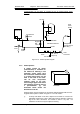
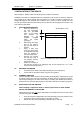
3.1 WALL MOUNTING BRACKET
a Place the bracket on
the wall horizontally
with the pre-drilled
holes at the bottom
and position as
dictated by the
template supplied
within the boiler
packaging.
b Drill through the centre
hole of the bracket,
plug the hole and fix in
position.
c Using a spirit level
make sure the bracket
is completely level and
mark the position of
the other screw holes.
d Remove the bracket
and drill the holes in
the positions marked.
Plug these holes.
e Screw the bracket to
the wall using screws of an appropriate size for the wall type (No. 12 x 2 inch
wood screws normally suffice).
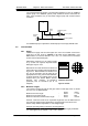
3.2 MOUNTING THE BOILER
a Lift and locate the boiler in the studs protruding from the wall bracket.
b Fix the boiler on the bracket studs using the nuts supplied.
3.3 ASSEMBLY PRACTICE
Remove all plastic debris and burrs when installing air intake piping. Plastic filings caused
by cutting muPVC pipe must not be allowed to be drawn into the combustion air blower.
Prevent dust entering the air intake when cutting on building sites. Blower failure which is
determined to be caused by plastic filings or other debris will not be covered by guarantee.
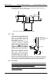
3.4 INSTALLING FLUE AND AIR PIPES
When installing a replacement boiler, a new flue system must be fitted. DO NOT
RE-USE THE ORIGINAL FLUE SYSTEM.
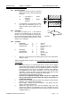
Remember the flue pipe must slope downwards back towards the boiler and this is best
achieved using 92.5
o
bends.
a Using the template supplied within the boiler packaging mark the positions of the
two holes for the flue and air pipes on the wall(s) or ceiling.
b Drill the two holes in the wall/ceiling, preferably using a core drill.
WD209/1/2000 Chapter 3 : Installation The Keston Celsius 25 & 25P
Installation & Servicing Instructions Page : 15
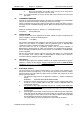
All dimensions in mm.
Figure 3.1 Wall Mounting Fixing Locations
191