
Installation Manual

air has been purged from the gas supply to the boiler. When the burner is lit and
the boiler is operating normally the yellow Boiler On LED will illuminate
continuously and the four green modulation LEDs will show the output level the
boiler has determined is necessary for the heating load. If an air lock or other
blockage is present the unit may go to overheat or water pressure lockout. If this
occurs clear the blockage and/or purge the air from the system, turn the user
control knob off (fully anticlockwise) and repeat the procedures.
If ignition does not occur, the boiler on (yellow) LED will be extinguished and, at
approximately 20 second intervals, the electronic ignition system will make four
further attempts to light the burner.
If the ignition is successful and the boiler is operating normally, the green (mains)
LED and the boiler on (yellow) LED will be illuminated simultaneously.
If after five automatic attempts the boiler still fails to ignite, the yellow (boiler on)
lamp will be extinguished and the red (lockout) lamp will flash twice every two
seconds.
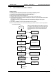
If, after five manual attempts (to allow for purging of any air in the gas line), the
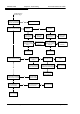
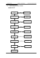
boiler still fails to ignite (indicated by the red (lockout) lamp) refer to Section 5.2 -
Fault Finding Flow Chart.
f. Check for gas soundness between the gas service cock and connection to
the burner manifold.
4.6 HOT FLUSHING
a. Allow the system to heat up, checking for water soundness.
b. Follow instructions provided with the cleaning agent, ie Fernox Supafloc, or
equivalent. Turn off the boiler and flush the water system while still hot.
Thoroughly flush the system with clear water.
c. Refill the system using a quality water treatment such as Fernox MB1. For sealed
systems, fill to the required Initial Design Pressure.
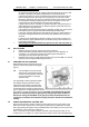
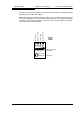
4.7 CHECKING THE GAS PRESSURE
With the boiler running measure the burner
pressure at the burner pressure test nipple.
(pos. 5).
NB: It is advisable to carry out this test
with the user control knob turned to
maximum and the system water cold
to ensure the boiler is running at
maximum rate.
The gas setting is factory adjusted to within
the required range and should not need
adjustment. If the reading is incorrect then
check such factors as soundness of the air
and flue pipe joints and the gas inlet pressure
(pos. 3) (minimum 18 mbar required for natural
gas, minimum 31 mbar required for LP gas). If all joints are sound and the gas inlet
pressure is satisfactory check the gas input by timing the gas meter as detail in
Section 4.8 Timing The Gas Meter. If the gas input cannot be measured then it’s
compulsory to measure the combustion quality as detail in Section 4.9 Combustion
Testing.
4.8 TIMING THE GAS METER - NATURAL GAS
After the boiler has been started, and with no other appliances using gas, time the gas
meter to be certain that the unit is running at the proper gas input. Determine the cubic
feet of gas passing through the meter and determine the input in Btu per hour. Input must
be within plus or minus 5% of the rated input.
Time, in seconds, the time taken to pass 2 cubic feet of gas through the meter (ie one
revolution of a 2 cu ft dial) or 0.1 cubic metres if the meter is of the new metric digital type.
WD209/1/2000 Chapter 4 : Commissioning The Keston Celsius 25 & 25P
Installation & Servicing Instructions Page : 20