
Installation Manual


WD485/0/2008
2/3
The procedure below details this setting using an electronic means of locking the boiler on
high or low fire rate. Where the instruction requires that the electrical supply to the appliance
is isolated, correct isolation procedures shall be followed. Always verify safe electrical
isolation before working on an appliance.
1. Electrically isolate the appliance, verify that the electrical supply has been isolated then remove
the appliance case by first removing the securing screws at the top and bottom of the appliance.
2. Once the casing has been removed keeping
your hands away from exposed electrical
components and connections, switch the
electrial power supply to the appliance back on.
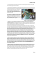
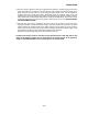
Prior to commencing the adjustment procedure,
the boiler should be brought up to the normal
working temperature, a gas working pressure of
at least 18mbar should be present at the gas
inlet test nipple (see Figure 1) and the thin
neoprene plastic pipe between the venturi and
gas valve should be in place/sound.
3. Turn off the boiler via the fascia control knob
and electrically isolate the boiler. Verify that the
electrical supply has been isolated.
Figure 1 - Gas Inlet PTN
4. The fascia panel containing the on/off knob should be removed via the four retaining screws.
Fascia PCB should have the electrical lead still connected and the knob left to the off position.
5. Please be aware that some of the C25 boilers are fitted with a plastic translucent moisture cover
over the top of the gas valve, this cover is held in place by a Phillips screw on the gas valve. Prior
to adjustment this shield should be removed.
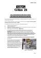
6. On the right hand board as you look at the
boiler face on, you will locate a small electrical
bridging jumper attached to the board. The
jumper is red in colour, approx 18mm in from
the front edge and 12mm up from the bottom
edge of the board (see Figure 2).
7. Please note : The following procedure shall
only be carried out by a trained and
competent operative. As the adjustment of the
gas valve high and low fire adjustment screw
must the indertaken with the appliance running,
precautions should be taken to avoid contact
with any exposed electrical components and
connections.
Figure 2 - PCB Fan Speed Jumper
To set the high fire adjustment you will need to lock the boiler in this mode. To achieve this you
need to remove the jumper from the board. Then, with the jumper removed, restore power to the
boiler. Keeping your hands out of the appliance whilst the electrical supply is on, turn the boiler on
and off using the facia control knob. On each operation of the knob to on then off, will result in the
illumination of one of the four lower green LEDs in succession. High fire is denoted when the third
lower green LED is illuminated. At this point electrically isolate the boiler, verify electrical isolation
and then fit the jumper back in its original position, restore power to the boiler and turn the boiler
on using the control knob. The boiler should go through its start up procedure and lock itself on
high fire with all four LEDs illuminated. The flue gas composition can now be tested via the flue
spiggot test point. A reading of 8.5% to 9% CO2 for natural gas (G20) boilers should be present,
or 9.5% to 10% CO2 for LPG (G31). If the CO2 is not found to be within this range, the gas valve
high fire adjustment screw should be turned to achieve this figure. This screw can be identified
from this manual, page 20, item number 8; in addition this screw is identified by the use of tamper
paint on the screw head.