FRAME & HEADER KIT INSTRUCTIONS Keston Heat 45 Keston Heat 55 Keston Heating PO Box 103, National Avenue, Kingston Upon Hull, HU5 4JN Tel. +44 (0) 1482 443005 Fax. +44 (0) 1482 467133 email : info@keston.co.uk web : www.keston.co.
This kit is suitable for the following boilers: Keston Heat 45 & 55 Contents 1 Introduction and General Description...........................3 2 General Description of Cascade System......................4 3 Multiple Boiler System Components.............................5 4 Installation Drawings for Multiple Boiler Systems.......8 5 Wall Mounted Installation Procedure.......................... 11 6 Frame Kit Installation Procedure.................................13 7 Header Kit Assembly....................
1 Introduction This technical data contains information for dimensioning & assembly of a cascade system kit for the Keston Heat range of products. Header and Frame kits are available in line (from 2 to 6 boilers long). General Description of Frame & Header kits A requirement to spread the total required heat output over several boilers can be accommodated by the use of the Keston Heat multiple boiler frame & header kit options.
2 General Description of Cascade Systems 2.1 Frame and header Kit Design Options The Keston Heat boilers are suitable for use in a multiple boiler configuration. The multiple boiler system is available as a wall or frame mounted side by side configuration with the use of the relevant frame / header kits. This gives opportunity to choose the optimum footprint size or wall space for a given output.
2.2 Multiple boiler Installations For installing 2 to 6 boilers, the product range includes water and gas headers capable of assembly using threaded socket,compression and flange connections. 2.3 Hydraulic isolation: Mixing header (Header Kits include a low loss mixing header) A low loss header allows flow separation within a hydronic system. This essentially creates linked stand alone flow circuits with their own flow rates and pressure drops.
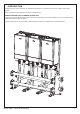
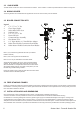
3.3 Gas header The Gas header consists of a custom manufactured 2” manifold. This is located in a cradle incorporated within the header mounting skid. 3.4 Mixing header The mixing headers are insulated and are supplied with an auto air vent and drain point as standard. 3.5 Boiler connection kits Legend 1. 11/4" x 3/4" x 11/4" Tee 2. Close Taper Nipple 3. Safety Relief Valve 6 bar 4. Isolation Valve 5. 11/4" x 1/2" x 11/4" Tee 6. Drain Off Cock 7. Connection Pipe Assembly 8. Non Return Valve 9.
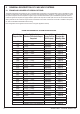
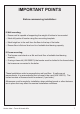
IMPORTANT POiNTS Before commencing installation: If Wall mounting; • Ensure wall is capable of supporting the weight of boilers to be mounted • Mark drill points of header using floor mounting template • Mark height on to the wall from the floor to the top of the boiler • Ensure floor is flat and level and is of suitable load bearing capacity If Frame mounting; • The frames must stand on a flat and level floor of suitable load bearing capacity.
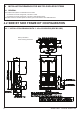
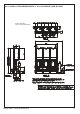
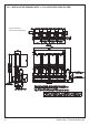
4 Installation drawings for Multiple boileR SYSTEMS 4.1 General The multiple boiler systems are available in two formats: • 2 to 6 boilers in a linear configuration, mounted on a wall. • 2 to 6 boilers in a linear configuration, mounted on free-standing frames. The boiler side of the cascade systems is sized to give a water flow and return differential 20ºC. 4.2 sIDE BY sIDE fRAME kIT cONFIGURATION 4.2.
4.2.
4.2.
4.2.
4.2.
5 Wall Mounted Installation procedure 5.1 Wall mounted side by side option Ensure wall is capable of supporting the weight of boilers to be mounted. Note. boiler weights can found in the boiler Installation Instructions. 1. Cut the sides off the cardboard wall mounting template/s (found in the boiler packaging) to create the 50mm side clearance required. 4. Drill the required holes in the wall to fit the wall mounting plate plugs. (See boiler Installation Instructions for details) 2.
5.1 Wall mounted side by side option cont'd............ SIDE VIEW PLAN VIEW Careful consideration MUST be given to the installation tolerances. If these are not adhered to, hoses may become kinked or connections may not fit. Bolt header to floor using template provided (front fixings only).
6 Frame Kit Installation Procedure 6.1 Side by side Frame kit mounting procedure 1. Place the frame kit sections in the required position and bolt them together at the top and bottom with the bolts, nuts and washers provided. 1 2 Keston Heat - Frame & Header Kits 2. If additional stability is required remove the plastic foot covers and drill the floor. Then bolt the frame to the floor using suitable bots and fixings (bolts not supplied).
6.2 Boiler mounting 1. As appropriate mount the boilers onto either the wall plates or the side by side frame kit. 1 2. Ensure the two boiler bottom fixing brackets are screwed to the frame or wall. 2 7 Header kit assembly 7.1 Fitting mixing header and blanking flanges 1. Fit the mixing header and blanking flanges in the chosen positions, with the bolts, washers and seals supplied. Note. Mixing header can be located either LHS or RHS of the headers.
7.2 Fitting header kit assembly 1. Slide the header kit assembly between the frame legs but do not screw the header kit to the frame at this stage. 1 2. Screw the header legs to the frame feet with the bolts, nuts & washers provided. Tighten nuts after the flexible hoses have been fitted to the boiler. 2 3. Fit the two flexible header connections to the boiler flow and return connections ensuring the sealing washers are fitted.
7.3 Fitting gas connection 1. Fit the gas isolation valve assembly supplied with the boiler to the boiler gas connection ensuring the sealing washer is fitted. 1 2. Fit the copper gas pipe provided in the header kit to the isolating valve and the header gas connection using 22mm compression fittings provided. 2 2 7.4 Pressure relief valve connection 7.5 Condensate Trap fitting 1. Ensure each boiler pressure relief connection is piped to a safe discharge point. 1.
8 Electrical Connections Refer to the Installer Wiring Connection section in the boiler Installation Instructions for wiring details. 9 commissioning and testing Electrical and gas safety checks must be carried out on completion of installation as with individual boiler commissioning.
Keston Heating, PO Box 103, National Avenue, Kingston Upon Hull, HU5 4JN Tel. +44 (0) 1482 443005 Fax. +44 (0) 1482 467133. www.keston.co.uk June 2013 UIN 209785 A01 Keston pursues a policy of continuing improvement in the design and performance of its products. The right is therefore reserved to vary specification without notice.