WD53/0/1999 The Keston 260 & 340 Condensing Boilers Fan Powered High Efficiency Commercial Condensing Gas Boiler Installation And Servicing Instructions Keston 260 Keston 340 PI No : 87AU111 GB/IE These instructions must be left either with the user or next to the site gas meter. 34 West Common Road Hayes, Bromley, Kent BR2 7BX Tel. +44 (0)208 462 0262 Fax. +44 (0)208 462 4459 e-mail: info@keston.co.uk http: //www.keston.co.
WD53/0/1999 The Keston 260 & 340 Condensing Boilers CONTENTS Section 1 Description 1.1 1.2 1.3 1.4 GENERAL INSTRUCTION Description Boiler Schematic Related Documents Performance Data 2.1 2.2 2.3 2.4 2.5 2.6 2.7 2.8 2.9 2.10 2.11 BOILER LOCATION Dimensions & Minimum Clearances Service Connections Position Electrical Gas Supply Water Systems Flue System Air Supply Compartment Installation Condensate Drainage Under Floor Heating/Weather Compensation 3.1 3.2 3.3 3.4 3.5 3.6 3.7 3.8 3.9 3.
WD53/0/1999 4.7 4.8 5 Combustion Fine Tuning Handing Over To The User 5.1 5.2 5.3 5.4 5.5 5.6 5.7 FAULT FINDING Electrical Control Sequence Fault Finding Flow Chart Continuity Checking Module Functional Flow Wiring Diagram Full Electrical Wiring Diagram Full Illustrated Wiring Diagram Exploded Assembly Diagrams 6.1 6.2 SERVICING Pre Service Checks Recommended Routine Service 7.0 7.1 7.2 7.3 7.4 7.5 7.6 7.7 7.8 7.9 7.10 7.11 7.12 7.
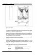
WD53/0/1999 Chapter 1 : General Instruction The Keston 260 & 340 Condensing Boilers 1. GENERAL INSTRUCTION 1.1 DESCRIPTION The Keston 260 and 340 Condensing Boilers are unique in their concept and design. They comprise two boiler modules with individual gas valve, fans, burners and heat exchanger assemblies. The two modules are fully independent in operation and are automatically sequenced to provide optimum load matching. In addition, firing sequence is regularly rotated to ensure even usage levels.
WD53/0/1999 Chapter 1 : General Instruction The Keston 260 & 340 Condensing Boilers Fig. 1.2 - Boiler Layout The condensate is very slightly acidic with a pH level of around 5 (about the same acidity as vinegar) and should be piped in a plastic pipe. It is not harmful to the waste disposal system and may be disposed of as normal waste water. The flue gases are piped in a 100mm composite plastic pipe to the outside.
WD53/0/1999 Chapter 1 : General Instruction CP342.
WD53/0/1999 Chapter 2 - Boiler Connections The Keston 260 & 340 Condensing Boilers 2. BOILER LOCATION All dimensions in mm. 2.1 DIMENSIONS AND MINIMUM CLEARANCES The boiler must be installed in minimum clearances shown to allow subsequent servicing, and safe operation. 2.2 SERVICE CONNECTIONS Gas, water, air and flue pipe, condensation, and electrical connections are as shown. Gas : 1.25 inch BSP female. Flow/Return 2 inch BSP female. 127 1 1 540 2.
WD53/0/1999 Chapter 2 - Boiler Connections The Keston 260 & 340 Condensing Boilers Before locating the boiler near a living space consider whether the sounds generated by the boiler will be objectionable. The boiler may be located within a cupboard enclosure to reduce noise levels if located within a living space. 2.4 ELECTRICAL 2.4.
WD53/0/1999 2.6 Chapter 2 - Boiler Connections The Keston 260 & 340 Condensing Boilers WATER SYSTEMS All piping must be installed in accordance with all applicable local and Water Supply Bylaws for forced hot water heating systems. Consideration must be given to pipe capabilities and pressure drop through the piping. Water treatment must be carried out to BS 7593 : Treatment of Water in Hot Water Central Heating Systems. Pump isolating valves must be positioned as close to the pump as possible.
WD53/0/1999 2.6.1 Chapter 2 - Boiler Connections The Keston 260 & 340 Condensing Boilers Open Vented Systems A typical system is shown in Figure 2.6.1 which includes a combined feed and vent. Note the valve between the boiler flow and the open vent is a three way blowdown type valve. Note that the minimum static head required is 3m at the top of the system pipework.
WD53/0/1999 Chapter 2 - Boiler Connections The Keston 260 & 340 Condensing Boilers All components of the system including the heat exchanger of any calorifiers used must be suitable for a working pressure of 3 bar and a temperature of 110 oC. Care should be taken in making all connections that the risk of leakage is minimised. 2.6.3 Hot Water System (if applicable) The hot water storage vessel must be of the indirect type). DIRECT CYLINDERS MUST NOT BE USED. Further guidance is provided in BS 1394. 2.
WD53/0/1999 2.6.7 Chapter 2 - Boiler Connections The Keston 260 & 340 Condensing Boilers Pump Selection The Keston 260 and Keston 340 boilers are supplied complete with integral boiler shunt pumps. However, these pumps are sized purely to provide adequate flow rate through the boiler at the pressure drop caused by the boiler itself. No allowance has be provided in the shunt pump size for system resistance.
WD53/0/1999 Chapter 2 - Boiler Connections The Keston 260 & 340 Condensing Boilers Example: FLUE Air inlet uses two one 92.5o sweep elbows. Hence, maximum length permissible (ie a+b in figure 2.8.2) = 20.0m - 1.0m - 1.0m = 18.0m Flue outlet uses one 92.5o sweep elbow. Hence, maximum length permissible (ie c+d in figure 7 = 40.0m - 1.0 m - total air inlet length = 39.0m - total air inlet length. d c b a Keston Figure 2.7.
WD53/0/1999 Chapter 2 - Boiler Connections The Keston 260 & 340 Condensing Boilers The flue outlet terminal is designed to face outwards but can, if desired, be adapted to face in any direction BUT must not be directed in the region of the air inlet. Where the air and flue terminals are located in close proximity the flue terminal should be located above the level of the air inlet terminal.
WD53/0/1999 Chapter 2 - Boiler Connections The Keston 260 & 340 Condensing Boilers External wall faces and any internal faces of cavity walls must be made good. 2.8 AIR SUPPLY The Keston is a room sealed appliance and therefore does not require purpose provided ventilation to the boiler room for combustion air. 2.9 COMPARTMENT INSTALLATION The casing temperatures of the Keston 260 and Keston 340 are very low. Due to this fact, no compartment ventilation is required for cooling purposes. 2.
WD53/0/1999 Chapter 3 : Installation The Keston 260 & 340 Condensing Boilers 3. INSTALLATION OF THE BOILER Read Chapter 2 - Boiler Location and decide upon the position of the boiler. Installation of the boiler is straightforward but consideration must be given to access to allow flue and air pipes to be pushed through walls and ceilings.
WD53/0/1999 3.6 Chapter 3 : Installation The Keston 260 & 340 Condensing Boilers a From the two connections on the boiler, mark the positions of the two holes for the flue and air pipes on the wall(s) or ceiling. To allow access to drill the holes it may be necessary to temporarily remove the boiler. If the boiler stays put then it is imperative that the front doors are closed and the two plastic pipes capped off whilst drilling.
WD53/0/1999 3.9 Chapter 3 : Installation The Keston 260 & 340 Condensing Boilers ELECTRICAL SUPPLY The entry point(s) for the electrical supply cable(s) is in the base of the appliance (see Section 2.2 Service Connections fig. 2.1.2) via two cord grip bushes. Feed the cable(s) through its bush and route inside the cabinet to the connection strip located to the front bottom right of the cabinet. 1. 2. 3. 4. The electrical supply must be as specified in Chapter 2 - Section 2.4 Electrical Supply.
WD53/0/1999 Chapter 3 : Installation The Keston 260 & 340 Condensing Boilers Reduce the pressure to the Initial System Design Pressure for sealed systems, if applicable. Vent the system. Gas Supply The complete gas installation up to the boiler service cock must be checked for soundness. BS 6891. Electrical Installation Carry out preliminary electrical safety checks, i.e. Earth continuity, Polarity, Resistance to Earth, Short Circuit using a suitable test meter.
WD53/0/1999 Chapter 4 : Commissioning The Keston 260 & 340 Condensing Boilers 4. COMMISSIONING OF THE BOILER Important: This condensing boiler contains components which could be damaged or blocked by grease, dirt, solder etc., from the water system. The following commissioning procedures must be followed precisely. 4.1 INITIAL FLUSHING All waterways within the Keston are either copper, bronze or high alloy stainless steel.
WD53/0/1999 f g h 4.5 The Keston 260 & 340 Condensing Boilers Set the left hand module on/off switch to "ON". The amber light will illuminate on the On/Off switch, the red “lockout” light will illuminate for approximately 2 seconds. The module blower and pump will start and, after about 15 seconds, a spark will light gas at the main burner, provided all air has been purged from the gas supply to the boiler.
WD53/0/1999 4.7 Chapter 4 : Commissioning The Keston 260 & 340 Condensing Boilers COMBUSTION FINE TUNING Although the gas pressure is preset at the factory differing flue arrangements may require fine tuning of the gas pressures to produce the best combustion and ensure long burner life. It is advisable to check proper combustion by measuring gas input and the level of carbon dioxide, or oxygen, in the flue outlet from the boiler.
WD53/0/1998 Chapter 5 : Fault Finding The Keston 260 & 340 Condensing Boiler 5. FAULT FINDING 5.1 ELECTRICAL CONTROL SEQUENCE When the power supply is established to the boiler and the main boiler on/off switch is in the "on" position the main on/off switch will be illuminated. Subsequently when the external controls are calling for heat, power will be fed back to the boiler connection strip at terminal 18.
WD53/0/1999 5.2 Chapter 5 : Fault Finding The Keston 260 and 340 Condensing Boiler FAULT FINDING FLOW CHART Apply power to boiler START Is main on/off switch light on ? N Is main on/off switch in "on" position ? Switch On N Check external power supply. Y N Y Is there 230VAC betw een connector strip terminals 1 and 2 ? Y Faulty switch neon Replace switch. Set external controls to on and turn off other module.
WD53/0/1998 Chapter 5 : Fault Finding The Keston 260 & 340 Condensing Boiler Continued from sheet 1. Is the module fan running ? N Is the integral sequence controller calling the module on? N * Boiler flow is too hot. Adjust set point higher or allow to cool or faulty sequence control. Y Is the module return thermostat closed ? Module return is too hot. Allow to cool or faulty thermostat - replace.
WD53/0/1999 Chapter 5 : Fault Finding The Keston 260 and 340 Condensing Boiler Continued from Sheet 2 Continued from sheet 1. Does the module ignition sequence start ? N Is the fan motor relay stuck ? Y Replace Relay. N N Switch off & if problem persisits replace control box.
WD53/0/1998 Chapter 5 : Fault Finding The Keston 260 & 340 Condensing Boiler Continued from Sheet 3 Continued on Sheet 3 Is module burner setting pressure as per spec. (Section 4.7)? N Adjust burner pressure Y Is the gas valve opening? Y Faulty gas valve or solenoid - replace.
WD53/0/1999 Chapter 5 : Fault Finding The Keston 260 and 340 Condensing Boiler Continued from sheet 4 Does flame stop after 5 to 10 seconds ? Y Is boielr earthed correctly? Earth Boiler Y Correct Wiring. Y N Are live and neutral supply lines crossed at main connection to boiler? N Is combustion and gas rate set correctly? N Set gas rate & combustion (Sections 4.7 and 4.
WD53/0/1998 Chapter 5 : Fault Finding The Keston 260 & 340 Condensing Boiler 5.3 CONTINUITY CHECKING To check continuity connect one probe to a neutral and use the other probe to check 230V AC START Is there 230V at terminals 1, 17 & 18? Check external controls and supply. N Y Is there 230V at the module ON/OFF sw itch (both terminals) ? N Faulty switch Replace Y Is there 230V at the module return thermostat (both terminals) ? N Thermostat tripped.
WD53/0/1999 5.
WD53/0/1998 5.
WD53/0/1999 5.
WD53/0/1998 5.7 Chapter 5 : Fault Finding The Keston 260 & 340 Condensing Boiler Exploded Assembly Diagrams 5.7.
WD53/0/1999 5.7.
WD53/0/1998 5.7.
WD53/0/1999 5.7.
WD53/0/1998 5.7.5 Chapter 5 : Fault Finding The Keston 260 & 340 Condensing Boiler Exploded Diagrams Parts Reference List Casing Assembly (Fig 5.7.1) GC Number Code 4 40 12 Description Cabinet Frame Name Plate Front Panel Waterway, Condensate & Flue Assembly (Fig. 5.7.
WD53/0/1999 Chapter 6 : Servicing The Keston 260 & 340 Condensing Boilers 6. ROUTINE (ANNUAL) SERVICING To ensure the continued safe and efficient operation of the boiler it is necessary to carry out routine servicing at regular intervals. The frequency of the servicing will depend upon the particular operating conditions, but it is recommended that an annual service should be carried out by a qualified engineer. It is the law that any service work must be carried out by competent qualified persons. 6.
WD53/0/1999 Pressure Test Point B Chapter 6 : Servicing The Keston 260 & 340 Condensing Boilers Flue Pressure Test Point A Heat Exchanger Shell Pressure Test Point C & Combustion Test Point Flue Overheat Thermostat Burner Heat (From Above) Fig 6.1.1 Module Pressure Test Point Locations 6.2 Recommended Routine Service The procedure detailed below should be carried out on each boiler module in turn. The integral boiler controller ensures both modules are loaded evenly over a year of operation. a.
WD53/0/1999 Chapter 7 : Replacement Of Parts The Keston 260 and 340 Condensing Boilers 7. REPLACEMENT OF PARTS INDEX 7.0 GENERAL 7.1 PRECAUTIONS 7.2 ACCESS 7.3 PROCEDURES - GENERAL 7.4 ELECTRICAL 7.4.1 ON/OFF SWITCH 7.4.2 BOILER THERMOSTAT 7.4.3 FLOW OVERHEAT, FLOW HIGH LIMIT & FLUE PROTECTION THERMOMSTATS 7.4.4 WATER PRESSURE SWITCH 7.4.5 IGNITION CONTROL BOX 7.4.6 AIR PRESSURE SWITCH 7.4.7 COMBUSTION BLOWER 7.4.8 GAS CONTROL VALVE 7.4.9 GAS LOW PRESSURE SWITCH 7.
WD53/0/1999 Chapter 7 : Replacement Of Parts The Keston 260 & 340 Condensing Boilers 7.0 GENERAL The following must always be carried out by a competent/qualified person. 7.1 PRECAUTIONS i) Always switch off the mains electricity supply ii) Gain access to the appliance (Section 7.2) and turn off the gas supply at the appliance service cock. WARNING : Parts of the boiler internal wiring will remain live even after turning the boiler ON/OFF switch to the OFF position.
WD53/0/1999 Chapter 7 : Replacement Of Parts The Keston 260 and 340 Condensing Boilers iv) 7.4.5 7.4.6 7.4.7 7.4.8 Drain the system to below the level of the appliance using the drain off tap at the base of each heat exchanger. v) Remove the push on connectors from the water pressure switch taking note of the correct positions. vi) Unscrew the pressure switch. vii) Reassemble (Section 7.3). viii) Refill the system (See Section 4 - Commissioning). Module Ignition Control Box (Fig. 5.7.
WD53/0/1999 7.4.9 7.5 viii) xii) Reassemble (Section 7.3) xiii) Reset the gas rate (See Section 4 - Commissioning) Module Gas Low Pressure Switch (Fig. 5.7.3 item 134) i) Isolate the appliance (Section 7.1) ii) Gain access (Section 7.2) iii) Remove the push on connectors to the gas low pressure switch taking note of the correct positions. iv) Unscrew the gas low pressure switch from the brass holder. v) Reassemble (Section 7.3) Isolate the appliance (Section 7.1) Gain access (Section 7.
WD53/0/1999 7.8 MODULE HEAT EXCHANGER (Fig. 5.7.2 item 77) i) ii) iii) iv) v) vi) vii) viii) ix) x) xi) xii) xiii) xiv) xv) xx) xxi) 7.9 Isolate the appliance (Section 7.1) Gain access (Section 7.2) Shut of the water supply to the appliance. Remove the burner head (Section 7.7) Drain the system to below the level of the appliance using the drain off tap at the base of the heat exchanger. Remove the boiler thermostat (Section 7.4.
WD53/0/1999 7.12 Isolate the appliance (Section 7.1) Gain access (Section 7.2) Unscrew the sight glass fitting from the burner head. Reassemble (Section 7.3) MODULE HT IGNITION LEAD (Fig 5.7.4 item 185) i) ii) iii) iv) 7.14 The Keston 260 & 340 Condensing Boilers MODULE SIGHT GLASS (Fig. 5.7.2 item 71) i) ii) iii) iv) 7.13 Chapter 7 : Replacement Of Parts Isolate the appliance (Section 7.1) Gain access (Section 7.2) Remove the lead from the electrode and the ignition control box.
WD53/0/1999 Chapter 8 : Spare Parts Listings The Keston 260 & 340 Condensing Boilers 8.
WD53/0/1999 Chapter 8 : Spare Parts Listings Part Denomination The Keston 260 & 340 Condensing Boilers Item GC No 99 375 534Flow High Limit Stat 142 375 535Gas Valve Outlet Gasket 136 375 536Gas Valve 147 114 122Flexible Hose Gasket 183 E01-074 202 - Air Pressure Switch Installation & Servicing Instructions Item 185 GC No Part Denomination Ignition Control Box E01-075 HT Ignition Cable Page : 46
WD53/0/1999 Chapter 8 : Spare Parts Listings The Keston 260 & 340 Condensing Boilers SHORT SPARE PARTS LIST FOR THE KESTON CONDENSING BOILER RANGE Item 74 73 68 67 147 84 86 97 99 142 136 183 202 185 GC No 114 118 375 527 114 122 375 530 375 532 375 533 375 534 114 139 375 536 E01-074 E01-075 Installation & Servicing Instructions Part Denomination Burner Burner Manifold Gasket Ignitor Gasket Ignitor/Sensor Probe Flexible Hose Gasket Boiler Thermostat Flue Thermostat Flow Overheat Thermostat Flow High
WD180/0/99 KESTON CONDENSING BOILERS IMPORTANT KESTON 260 & 340 INSTALLATION KEY POINTS † † † † † † † † † † † † † † † † Read Installation Manual Carefully Ensure that there is at least 9 feet head of water pressure at the top of the boiler. Ensure that the boiler(s) is connected to the system via a low loss balance header. DO NOT remove the dust caps from the air and exhaust pipes until ready to connect. Ensure that ALL dust particles, filings , plastic chips etc. are removed from the inlet pipe.