
User Instructions

6.2 Recommended Routine Service
The procedure detailed below should be carried out on each boiler module in turn. The
integral boiler controller ensures both modules are loaded evenly over a year of operation.
a. Remove the burner head (Section 7.7) and inspect the burner appearance. Black
markings or other discolourations on the gauze indicate too much gas or a lack of
air. Any breakages or damage to the burner mesh indicate the burner must be
replaced.
b. If necessary, either due to discolouration or a high pressure differential between
points A & B in the pre-service checks, clean the burner with a mild
household
detergent and rinse under a hot running tap.
c. If necessary, either from visual inspection or a high pressure differential between
points B & C in the pre-service checks, clean the heat exchanger using a suitable
stiff plastic bristle brush, vacuum out any large particles and flush the heat
exchanger with fresh water until the water flowing from the condensate drain is
clear.
d. Remove the condensate trap (Section 7.10) and clean by flushing through with
clean running water.
e. Check the electrode mounted on the burner head. If the point is damaged or
burnt replace it.
Check that the spark gap measures 4 mm.
f. Replace the burner head, renewing the gasket if necessary, and reconnect the
gas/air supply and the ignition lead. Ensure the flanged gas/air supply joint is air
tight.
g. Turn on the electrical supply to the boiler and allow the boiler to reach operating
temperature levels.
h. Visually inspect the burner through the glass spy hole at the burner head (a small
mirror will prove useful).
i. Recheck the burner pressure by following the procedure detailed in Section 4.7
j. Remove the combustion test point plug from the flue pipe. This is situated around
150mm (6ins) from the bottom of the flue elbow at its connection to the heat
exchanger.
k. Using an approved combustion tester sample the flue products via the
combustion test point. CO
2
levels of between 8.2% and 8.5% should be observed.
If such levels are not observed tune the combustion as described in Chapter 4 -
Commissioning. Also check the gas flow as detailed in Sections 4.8 and 4.9
l. Replace the combustion test point plug.
m. Check all joints for soundness up to the gas burner.
n. Repeat the procedure for the other module.
WD53/0/1999 Chapter 6 : Servicing The Keston 260 & 340 Condensing Boilers
Installation & Servicing Instructions Page : 36
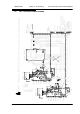
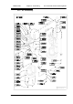
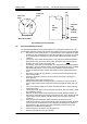
Pressure Test
Point B
Pressure Test
Point A
Burner Heat (From Above)
Pressure Test
Point C
Combustion
Test Point
Flue Overheat
Thermostat
Heat
Exchanger
Shell
Flue
Fig 6.1.1 Module Pressure Test Point Locations
&