KD-IP822ENC/DEC 4K Enterprise AV™ over IP Encoder/Decoder, PoE, HDMI Pass-Thru, 2x IR/RS-232 ports Quick Setup Guide The Experts in Digital Video Technology and Solutions™
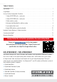
4 Table of Contents Key Features . . . . . . . . . . . . . . . . . . . . . . . . . . . . . . . . . . . . . . . . . . . . . . . . . . . . . . . . . . . . . . . . . . . 1 Usage Modes . . . . . . . . . . . . . . . . . . . . . . . . . . . . . . . . . . . . . . . . . . . . . . . . . . . . . . . . . . . . . . . . . . . 2 Unit and System Configuration Procedure . . . . . . . . . . . . . . . . . . . . . . . . . . . . . . . . . . . . . . . . . . . . . . . 4 1. Setup all ENCODER units – one by one . . . . . . . . .
1 Key Features ›› Enterprise AV™ Over IP: Utilizes a managed gigabit network switch to enable video distribution, matrix switching, and extension ›› Inter-System Compatibility: Fully compatible with KD-IP922ENC and DEC units / systems ›› Video Wall Processing: Encoder + Decoder systems create video walls with up to 4 total displays.
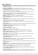
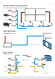
2 Digital Video Matrix: RS232 RS232 HDMI KD-IP822DEC RS232 HDMI KD-IP822DEC RS232 HDMI KD-IP822DEC HDMI KD-IP822DEC RS232 RS232 HDMI KD-IP822DEC RS232 HDMI KD-IP822DEC HDMI KD-IP822DEC TCP/IP Managed Gigabit Switch TCP/IP WiFi Router TCP/IP WiFi System Setup KD-IP822ENC KD-IP822ENC HDMI HDMI Camera IR/RS232 Cable/Satellite KD-IP822ENC System Control KD-IP822ENC HDMI HDMI Digital Signage PC KDMS™ Pro Key Digital® App Digital Video Distribution System HDMI IR/RS
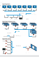
3 Video Wall Controller (4 displays maximum) HDMI KD-IP822ENC Digital Signage HDMI KD-IP822ENC Signage PC 1 HDMI HDMI RS232 HDMI RS232 HDMI RS232 KD-IP822ENC HDMI IR/RS232 RS232 Cable/Satellite HDMI KD-IP822ENC Operator Station (PC) KD-IP822DEC KD-IP822DEC KD-IP822DEC KD-IP822DEC TCP/IP Digital Video Extender Cable/Satellite TCP/IP KD-IP822ENC HDMI HDMI Up to 330 ft / 100 m @ 4K KD-IP822DEC Master Controller Satellite (8) Dimmable Lights RS232 Lighting HDMI HDMI KD-IP822ENC
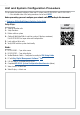
4 Unit and System Configuration Procedure This procedure documents building a Video over IP system using KD-IP822ENCs and KD-IP822DECs. »» A less detailed video of the setup procedure can be found HERE Before proceeding, you must configure your network switch according to this document: ›› Enterprise AV Verified Network Switcher Setup Guide Setup KeySteps: Digital® App 1. 2. 3. 4.
5 Test for proper operation of the unit and cables in your system before permanently securing the unit for final installation. Ensure that you leave enough ventilation space to provide sufficient airflow and cooling. 1. Setup all ENCODER units – one by one a. Connect one ENC unit to network switch using CAT6 cable. »» i. Note: Power supply sold separately for non-PoE switch systems b. Connect ENC to PC using USB c. Open Key Digital Management Software™ Pro (KDMS™ Pro) d. Detect unit: SCAN -> USB DEVICE e.
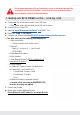
6 2. Setup all DECODER units – one by one a. Connect one DEC unit to network switch using CAT6 cable. »» i. Note: Power supply sold separately for non-PoE switch systems b. Connect DEC to PC using USB c. Open Key Digital Management Software™ Pro (KDMS™ Pro) d. Detect unit: SCAN -> USB DEVICE e. Configure Unit. Refer to completed KD-IP822 System Configuration Questionnaire. ›› Save (blue save icon) after updating each property cell »» i. Enter Device Name »» Desired “friendly name” of video source »» ii.
7 3. Define switcher system a. b. c. d. e. f. g. h. Connect all ENC and DEC units to network switch using CAT6 cables In KDMS™ Pro: SYSTEM -> AUTO-BUILD SYSTEM Name: ie “Dakota Dunes 17x29” Starting Group ID will always start at 1 unless otherwise noted Number of Inputs: How many Encoders in system Number of Outputs: How many Decoders in system Press OK All devices will move into the IP System workspace window, and will be green indicating a link to the physical device. i.
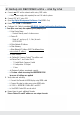
8 4. (Optional) Add Video Walls to switcher system a. Click the Add Video Wall button b. c. d. e. Enter friendly name for video wall (ie East Lobby) Starting Display is Device ID number of the top-left display / decoder in the video wall Enter number of horizontal and vertical displays and press OK Now the displays within the video wall appear as one output f. The video wall may be controlled by pressing the VIDEO WALL button at bottom center of the screen.
9 5. Load switcher file to units a. b. c. d. e.
10 6. Verify HDMI switcher system functionality a. b. c. d. e. Connect HDMI video sources to Encoders Connect HDMI displays to Decoders Connect all Encoders and Decoders to the network switch SCAN -> NETWORK SCAN Use the ALL OUTPUTS button in the control GUI section and verify successful video switching and signal by beginning with Source 1 and advancing to source 2, 3, 4, etc. Visit keydigital.com for a Complete Manual Please visit www.keydigital.com for the full manual and software downloads.
11 Important Product Warnings: 1. Connect all cables before providing power to the unit. 2. Test for proper operation before securing unit behind walls or in hard to access spaces. 3. If installing the unit into wall or mounting bracket into sheet-rock, provide proper screw support with bolts or sheet-rock anchors. Safety Instructions: Please be sure to follow these instructions for safe operation of your unit. 1. 2. 3. 4. 5. 6. Read and follow all instructions. Heed all warnings.
12 Contacting Key Digital® Technical Support For technical questions about using Key Digital® products, please contact us at: ›› Phone: 914-667-9700 ›› E-mail: tech@keydigital.com Repairs and Warranty Service Should your product require warranty service or repair, please obtain a Key Digital® Return Material Authorization (RMA) number by contacting us at: ›› Phone: 914-667-9700 ›› E-mail: rma@keydigital.
13
Rev 0 – June 2019 Key Digital®, led by digital video pioneer Mike Tsinberg, develops and manufactures high quality, cutting-edge technology solutions for virtually all applications where high-end video and control are important. Key Digital® is at the forefront of the video industry for Home Theater Retailers, Custom Installers, System Integrators, Broadcasters, Manufacturers, and Consumers. Key Digital® :: 521 East 3rd Street :: Mount Vernon, NY 10553 Phone : 914.667.9700 Fax : 914.668.