Verified Network Switches for use with Key Digital AV over IP Systems Supported Models: 4K Systems: KD-IP922ENC, KD-IP922DEC KD-IP822ENC, KD-IP822DEC KD-IP1022ENC, KD-IP1022DEC 1080p Systems: KD-IP1080Tx, KD-IP1080Rx KD-IP120Tx, KD-IP120Rx, KD-IP120POETx, KD-IP120POERx Important Note: Setup is different for 4K (KD-IP922, KD-IP822, KD-IP1022) and 1080p (KD-IP1080, KD-IP120) systems. There are separate setup instructions for each where applicable. 1. 2. 3. 4. 5. 6. 7. 8. 9. 10. 11. 12. 13. 14. 15. 16. 17.
Supported Models: Key Digital AV over IP product family consists of many different models. Not all models are compatible together See Key Digital AV over IP Solutions Selection Guide for more info System Facts 4K Systems: KD-IP822, KD-IP922, KD-IP1022 models • Video Compression Standard: Motion JPEG 2000 • Data Stream Bandwidth: < 900 Mbps Stream Resolution 4K @ 60Hz/30Hz 1080p @ 60Hz 1080i / 720p @ 60Hz • • • Bandwidth ≤ 850 Mbps ≤ 250 Mbps ≤ 125 Mbps Latency: ≈ 40ms @4K. Less at lower resolutions.
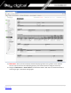
Network switch Requirements for Key Digital AV over IP Systems Key Digital’s AV over IP systems utilizes multicasting technology to broadcast streams throughout the network. Key Digital’s AV over IP systems require a network switch with IGMP (Internet Group Management Protocol) support in order to direct traffic of the broadcasted streams, ensuring that only the desired decoders receive the stream from the selected encoder.
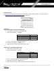
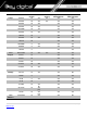
Brand Model Araknis AN-210-SW-R-8POE AN-210-SW-F-8POE AN-210-SW-R16-POE AN-210-SW-F16-POE AN-210-SW-R24-POE AN-210-SW-F24-POE AN-210-SW-F48-POE AN-310-SW-R-8 Port Number 8 Verified Network Switches PoE 10G Fiber Stacking YES Approved for KD-IP1080/120 YES Approved for KDIP822/922/1022 YES 8 YES YES YES 16 YES YES YES 16 YES YES YES 24 YES YES YES 24 YES YES YES 48 YES YES YES 8 YES YES AN-310-SW-F-8 8 YES YES AN-310-SW-R-16 16 YES YES AN-310-SW-F-16 16 YES YES
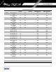
Brand Model Cisco SF500-48 Port Number 48 PoE 10G Fiber Stacking Approved for KD-IP1080 YES Approved for KDIP822/922/1022 NO YES YES YES YES YES YES YES YES YES YES YES YES YES SG300-28 Catalyst 3850 Series D-Link Engenius Niveo YES DGS-3630-52PC 52 YES DGS-3630-52TC 52 DGS-3630-28PC 28 DGS-3630-28SC 28 YES YES YES DGS-3630-28TC 28 YES YES YES DGS-3130-54PS 54 YES YES YES EGS5212P 8 YES YES NO EGS7228FP 24 YES YES NO EGS7252FP 24 YES YES NO EWS1
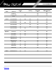
Brand Model YES 10G Fiber Stacking YES Approved for KD-IP1080/120 YES Approved for KDIP822/922/1022 YES Linksys 28 YES YES YES YES LGS326P 26 YES YES YES LGS318P 18 YES YES YES LGS326MP 26 YES YES YES LGS326P 26 YES YES YES LGS326 26 YES YES LGS318P 18 YES YES LGS318 18 YES YES LGS308MP 8 YES YES YES LGS308P 8 YES YES YES LGS308 8 YES YES Luxul AMS-4424P 24 YES YES Netgear GS716T 16 YES YES GS724T 24 YES YES GS748T 48 YES YES GS752T
IGMP Setup Guide: Araknis 1080p Systems (KD-IP1080, KD-IP120) 1. Before Araknis network switch is configured Key Digital KD-IP120/KD-IP1080 HDMI switch set must be connected to all HDMI sources/displays/network switches, and configured using Key Digital KD-IP120 Key Digital Management Software latest version; refer to Key Digital KD-IP120/KD-IP1080 configuration manual. 2. Power-up all the system components.
10. Navigate to Settings -> System. Under IP Address Settings elect Static. Change an IP address to 192.168.1.251, Subnet Mask to 255.255.255.0, Default Gateway to 192.168.1.1 (in this case), and at the bottom click Apply. If you are setting up multiple network switches it is recommended to set first one to 192.168.1.251, second to 192.168.1.252, and so on, and each switch must be set individually same way as described below.
11. Page will refresh. Configure your PC’s IP address to the same range as the switch (default 192.168.1.xxx). Enter the switch’s IP address (default is 192.168.1.251) in your browser and press ENTER. 12. Make sure the settings remain as above. 13. Navigate to Advanced -> Multicast -> IGMP Snooping. Under Settings select Enable for Status, V3 for Version, and Enable for Report Suppression. Under VLAN Settings / VLAN ID 1 select Enable for IGMP Snooping Status and Enable for Fast Leave.
14. IMPORTANT: At this point all the displays should be displaying stable running video from the selected sources. If you do not have them displaying properly, than network switch is configured incorrectly. 15. Navigate to Maintenance -> Restart Device and click Restart Switch. After switch is rebooted and back to normal log in again, check all the settings again.
16. IMPORTANT: Now you can connect back you DHCP equipment (routers, servers and so on). 17. Power down Araknis network switch and power it up back again. Wait for the whole system to start and until you can see video on your displays. 18. Log in to your Araknis network switch again and make sure that IGMP settings are intact. 19. Rescan your components with Key Digital KD-IP120 Key Digital Management Software and make sure HDMI video switch is functional. 20.
IGMP Setup Guide: Araknis 4K Systems (KD-IP822/922/1022) 1. Before Araknis network switch is configured Key Digital KD-IP120/KD-IP1080 HDMI switch set must be connected to all HDMI sources/displays/network switches, and configured using Key Digital KD-IP120 Key Digital Management Software latest version; refer to Key Digital KD-IP120/KD-IP1080 configuration manual. 2. Power-up all the system components.
10. Navigate to Settings -> System. Under IP Address Settings elect Static. Change an IP address to 192.168.1.251, Subnet Mask to 255.255.255.0, Default Gateway to 192.168.1.1 (in this case), and at the bottom click Apply. If you are setting up multiple network switches it is recommended to set first one to 192.168.1.251, second to 192.168.1.252, and so on, and each switch must be set individually same way as described below.
11. Page will refresh. Configure your PC’s IP address to the same range as the switch (default 192.168.1.xxx). Enter the switch’s IP address (default is 192.168.1.251) in your browser and press ENTER. 12. Make sure the settings remain as above. 13. Navigate to Advanced -> Multicast -> IGMP Snooping. Under Settings select Enable for Status, V2 for Version, and Enable for Report Suppression. Under VLAN Settings / VLAN ID 1 select Enable for IGMP Snooping Status and Enable for Fast Leave.
14. Enter Settings -> Ports and set Jumbo Frame size to 9216 bytes, enabling the required 8K jumbo frame support feature.
15. IMPORTANT: At this point all the displays should be displaying stable running video from the selected sources. If you do not have them displaying properly, then network switch is configured incorrectly. 16. Navigate to Maintenance -> Restart Device and click Restart Switch. After switch is rebooted and back to normal log in again, check all the settings again. 17. IMPORTANT: Now you can connect back you DHCP equipment (routers, servers and so on). 18.
IGMP Setup Guide: Cisco SF500-48, SG300 1080p Systems (KD-IP1080, KD-IP120) Note: Compatible with KD-IP1080, KD-IP120 Enterprise AV Systems Only 1. Before Cisco network switch is configured Key Digital KD-IP120/KD-IP1080 HDMI switch set must be connected to all HDMI sources/displays/network switches, and configured using Key Digital KD-IP120 Key Digital Management Software latest version. 2. Power-up all the system components.
11. Change Password screen will appear. Enter old and then new password two times as at the picture below and click Apply.
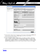
12. Getting Started screen will appear. 13. Navigate to Administration -> Management Interface -> IPv4 Interface. Select “1” under Management VLAN. Select Static for IP Address Type. Change an IP address to 192.168.1.251. If you are using multiple network switches it is recommended to set first one to 192.168.1.251, second to 192.168.1.252, and so on. Leave Network Mask as 255.255.255.0, set Administrative Default Gateway as User Defined and enter your router IP address (in this case: 192.168.1.
14. Click OK to confirm. 15. Log in again using new password and new IP address.
16. Confirm all the administration page settings as at the picture below.
17. Navigate to Multicast -> Properties. Check Enable box next to the Bridge Multicast Filtering Status box. Make sure the other settings are exactly as shown below. Then click Apply. 18. Navigate to Multicast -> IGMP Snooping. Check the IGMP Snooping Status: Enable box and click Apply.
19. Click on a radio button on the left and then click Edit. New window will appear. 20. Click on a radio button on the left and then click Edit. New window will appear. Select “1” for VLAN ID. Check Enable box under IGMP Snooping Status. Check Enable box under Immediate Leave. Check Enable box under IGMP Querier Status. Select User Defined next to Administrative Querier Source IP Address: and select 192.168.1.1. For IGMP Querier Version: select IGMPV3. Then click Apply and Close.
22. On the top of the page click on flashing “x Save”. For Source File Name: select Running configuration. For Destination File Name: select Startup configuration. Check the selections and make sure they are exactly as shown below. Click Apply. 23. Click Apply to confirm.
24. Click Done. 25. IMPORTANT: Now you can connect back you DHCP equipment (routers, servers and so on). 26. Power down Cisco network switch and power it up back again. Wait for the whole system to start and until you can see video on your displays. 27. Log in to your Cisco network switch again and make sure that IGMP settings are intact: 28. Rescan your components with Key Digital KD-IP120 Key Digital Management Software and make sure HDMI video switch is functional. 29.
IGMP Setup Guide: Cisco C3850 Series 4K Systems (KD-IP822/922/1022) Cisco Catalyst 3850 series This guide describes how to use Express Setup to initially configure your Catalyst 3850 switch. We have modified original Express Setup guide from Cisco to help out you install it easily. For more installation and configuration information, see the Catalyst 3850 documentation on Cisco.com.
Step 4 Power the switch. AC power switches: Plug the AC power cord into the switch power supply and into a grounded AC outlet. DC power switches: See the wiring instructions in Step3 Step 5 Observe the POST results. Approximately 30 seconds after the switch powers on, it begins the power-on self-test (POST), which can take up to 5 minutes to complete. During POST, the SYSTEM LED blinks green. When POST is complete, the SYSTEM LED turns solid green.
Step 8 Run command shell on your PC or laptop and enter “ipconfig” on the command line. You will get Windows IP configuration and find IP address of Default Gateway. Note. According to Express Setup from Cisco, it said “10.0.01” is default IP address. But it’s not correct for all Cisco Catalyst 3850 series. It looks default IP address will be varied depend on Cisco Switches.
Step 9 Start a browser session on the PC or laptop, and enter the IP address of your Default Gateway. Note: As I mentioned on Step8, your IP address of Default Gateway may differ with our IP address. When a pop-up dialog window “Connect to 10.0.2.
Note. Please do not click “Submit” button in this step. Step 12 Select the Advanced Settings tab on the Express Setup window • In the Telnet Access field, click Enable to use Telnet to manage the switch by using the command-line interface (CLI). If you enable Telnet access, you must enter a Telnet password. • In the Telnet Password field, enter a password.
Step 13 After you click Submit : • The switch is configured and exits Express Setup mode. • The browser displays a warning message and tries to connect with the earlier switch IP address. Typically, connectivity between the PC or laptop and the switch is lost because the configured switch IP address is in a different subnet from the IP address on the PC or laptop. Now, change IP address of your PC or laptop to static IP address in same subnet of the Switch.
Step 15 When you connect to the switch via Telnet successfully, you have to log in to Telnet server of the switch. 15-1. Enter your Telnet password you assigned at Step12 if prompted. 15-2. Enter “enable” on Switch> prompt to enable privileged EXEC mode 15-3. Enter your Telnet password once again. Then ‘Switch>’ prompt will turn into ‘Switch#’ prompt as below. Step 16 To Enable Jumbo Frame for IP922. Note: IP922 requires Jumbo Frame(8K) for video/audio transmission via 1G-BaseT with the Switch. 16-1.
Step 17 To confirm Jumbo Frame setting on the switch. 17-1.
Step 18 To Enable Multicast IGMP Snooping for IP922. Note: IP922 requires Multicast IGMP Snooping for matrix switch configuration. 18-1. Enter “configure terminal” on Switch# prompt 18-2. Enter “ip igmp snooping” on Switch(config)# prompt 18-3. Enter “ip igmp snooping vlan 1” on Switch(config)# prompt 18-4. Enter “ip igmp filter” on Switch(config)# prompt 18-5. Enter “ip igmp snooping tcn query solicit” on Switch(config)# prompt 18-6. Enter “ip igmp snooping querier” on Switch(config)# prompt 18-7.
Step 19 To confirm multicast IGMP Snooping setting on the switch. 19-1. Enter “show ip igmp snooping detail” on Switch# prompt You can check global IGMP Snooping configuration on the switch.
| P a g e Back to top
D-Link DGS-3630 Series Network Setup Guide Login to the switch: 1. Plug an Ethernet cable into any of the ports of the switch 2. Plug the other end into the Ethernet port of your computer 3. Power on the switch 4. Check to see that the IP address of the computer is within this network Subnet: 10.90.90.xxx (“xxx” ranges 1~254). For example, 10.90.90.
5. Open the Web browser and enter 10.90.90.90 (default IP address of D-Link DGS-3630-52PC). The login window appears as below. 6. Leave the user name and password fields empty. They are NOT required. Click “Login” to login to the switch configuration window. Enable Jumbo Frame: 7. Find System -> Port Configuration -> Jumbo Frame in the menu on left side of the window. (IP922 requires Jumbo Frame(8K) for video/audio transmission via 1G-BaseT).
8. Select the last 52 port “eth 1/0/52” in the menu on To Port, then enter “12288” in Maximum Frame Size on the right side of the Jumbo Frame window as below. And then click “Apply” button.
9. After applying, you should see Maximum Receive Frame Size 12288 for all ports as below. Enable IGMP Snooping: 10. Find L2 Features -> L2 Multicast Control -> IGMP Snooping -> IGMP Snooping Settings in the menu on left side of the window. (KD-IP922 requires IGMP Snooping for multicasting video/audio transmission via 1G-BaseT). Check the Global State Enabled box of Global Settings in IGMP Snooping Settings window as below. Click “Apply” button on the right side of IGMP Snooping Settings window. 11.
12. Click “Edit” button in IGMP Snooping Settings window. 13.
Network IP Settings: 14. Find L3 Features -> Interface -> IPv4 Interface. Select “Edit” button. This D-Link switch series can be set to IP address range 10.x.x.x. ONLY. If you use a single network switch, you may not need to change network IP settings. But if you are stacking network switches (connecting multiple network switches through D-Link 10G fiber cables), it is recommended to set first on to 10.90.90.91, second to 10.90.90.92, and so on. Set Get IP From “Static”, set Subnet Mask to 255.0.0.
15. To save all Running Configurations to Startup-Configuration, Find Save Save Configuration in the menu on top of the window. Then click “Apply” button in Save Running Configuration to startup-config window. 16. To reboot the switch, Find Tool Reboot System in the menu on top of the window. Then click “Reboot” button in Reboot System window. The switch will be rebooted automatically.
IGMP Setup Guide: Engenius 1080p Systems (KD-IP1080, KD-IP120) 1. It is recommended to reset the switch to factory defaults before configuring for multicast operation. Power up the device, wait for about 2 minutes, using a paper clip press and hold a reset button for more than 10 seconds and then release. After device is rebooted power down and then power up the device. Wait while the device is restarted and ready to use. 2. Connect your PC to the switch directly using a network cable. 3.
6. On the left select Switch. Navigate to System -> IP Settings -> IPv4. Under Auto Configuration select Static. Change an IP address to 192.168.1.250, Subnet Mask to 255.255.255.0, Default Gateway to 192.168.1.1 (in this case), and at the bottom click Apply. 7. Page will refresh. Configure your PC’s IP address to the same range as the switch (default 192.168.1.xxx). Enter the switch’s IP address (default is 192.168.1.250) in your browser and press ENTER. Log in again with the same user name /password.
8. On the left select Switch. Navigate to L2 Feature -> IGMP Snooping -> Global Settings. Under Status select Enabled, under Version: V2 and under Report Suppression: Enabled. Click Apply.
9. Navigate to L2 Feature -> IGMP Snooping -> VLAN Settings. Click on Edit button on the right in the VLAN ID 1 line. Under IGMP Snooping Status select Enabled, under Fast Leave select Enabled. Click check mark button to apply settings. 10. Now the switch should work properly with IP audio/video equipment.
IGMP Setup Guide: Linksys 1080p Systems (KD-IP1080, KD-IP120) 1. Before Linksys network switch is configured Key Digital KD-IP120/KD-IP1080 HDMI switch set must be connected to all HDMI sources/displays/network switches, and configured using Key Digital KD-IP120 Key Digital Management Software latest version. 2. Power-up all the system components. Using Key Digital KD-IP120 Key Digital Management Software, switch All Outputs -> Through at switching page. 3.
11. Navigate to Configuration -> IP Interface -> IPv4-> IPv4 Interface. Select Static IP Address. IP address can be changed by the administrator depending on the network configuration. If you are using multiple network switches it is recommended to set first one to 192.168.1.251, second to 192.168.1.252, and so on (we will leave the IP address unchanged). Set Subnet Mask to 255.255.255.0, set User Defined Default Gateway to 192.168.1.
13. Navigate to Multicast -> Future Configuration. Select Enable under Bridge Multicasting Filtering and click Apply. 14. Navigate to Multicast -> IGMP Snooping. Select Enable under IGMP Snooping, click Apply.
15. Click on radio button and click Edit. Edit IGMP Snooping window will appear. Make sure VLAN ID <1> is selected. Enable all the settings as shown below. Select IGMP v3 as IGMP Querier Version, Click Apply and then Close. 16.
17. IMPORTANT: At this point all the displays should be displaying stable running video from the selected sources. If you do not have them displaying properly, than network switch is configured incorrectly. 18. Navigate to Maintenance -> File Management -> Configuration File Copy. Select radio buttons as shown below, click Apply. This will save current configuration and will apply this configuration every time switch is powered up. 19.
21. Log in to your Linksys network switch again and make sure that IGMP settings are intact: 22. Rescan your components with Key Digital KD-IP120 Key Digital Management Software and make sure HDMI video switch is functional. 23. At this point your Linksys network switch is set and ready to use.
IGMP Setup Guide: Linksys 4K Systems (KD-IP822, KD-IP922, KD-IP1022) 1. Before Linksys network switch is configured Key Digital KD-IP922 HDMI switch set must be connected to all HDMI sources/displays/network switches, and configured using Key Digital Management Software latest version. 2. Power-up all the system components. Using Key Digital Management Software, switch All Outputs -> Through at switching page. 3.
11. Navigate to Configuration -> IP Interface -> IPv4-> IPv4 Interface. Select Static IP Address. IP address can be changed by the administrator depending on the network configuration. If you are using multiple network switches it is recommended to set first one to 192.168.1.251, second to 192.168.1.252, and so on (we will leave the IP address unchanged). Set Subnet Mask to 255.255.0.0, set User Defined Default Gateway to 192.168.1.
13. Navigate to Port Management -> Ports. Select Enable under Jumbo Frames and click Apply.
14. Navigate to Multicast -> Future Configuration. Select Enable under Bridge Multicasting Filtering and click Apply.
15. Navigate to Multicast -> IGMP Snooping. Select Enable under IGMP Snooping, click Apply.
16. Click on radio button and click Edit. Edit IGMP Snooping window will appear. Make sure VLAN ID <1> is selected. Enable all the settings as shown below. Select IGMP v2 as IGMP Querier Version, Click Apply and then Close.
17.
18. Navigate to Maintenance -> File Management -> Configuration File Copy. Select radio buttons as shown below, click Apply. This will save current configuration and will apply this configuration every time switch is powered up. 19. IMPORTANT: Now you can connect back you DHCP equipment (routers, servers and so on). 20. Power down Linksys network switch and power it up back again. Wait for the whole system to start and until you can see video on your displays.
21.
22. IMPORTANT: At this point all the displays should be displaying stable running video from the selected sources. If you do not have them displaying properly, than network switch is configured incorrectly 23. Rescan your components with Key Digital KD-IP922 Management Software and make sure HDMI video switch is functional. 24. At this point your Linksys network switch is set and ready to use.
Luxul AMS-4424P Network Setup Guide for KD-IP822, KD-IP922, KD-IP1022, KD-IP1080 Important Notes: • Please use firmware v.4.0.8.1. Other firmware versions are not compatible. • Verified for single switch use only. Stacking switches may cause compatibility issues. 1. Login to the switch: a. b. c. d.
3. Enter the user name and password. (default user name and password are both set as “admin”), then click “OK” to login to the switch configuration window. 4. Ensure all ports have Maximum Frame Size of 10056 entered as below. To check it, find Configuration Ports Ports in the menu on left side of the window. (KD-IP922 requires Jumbo Frame(8K) for video/audio transmission via 1G-BaseT). 5.
IGMP Snooping Configuration window. And check the Fast Leave box for all Ports related Configuration in the same window as below. 6. Click “Save” button on the bottom of IGMP Snooping Configuration window 7. To add VLAN of the IGMP Snooping at the switch, Find Configuration IPMC IGMP Snooping VLAN Configuration in the menu on left side of the window. (VLAN must be added in IGMP Snooping), then click “Add New IGMP VLAN” if there is not any specified VLAN in IGMP Snooping VLAN Configuration window.
Step 11. Then enter “1” in VLAN ID, check the box of Snooping Enabled and Querier Election in new VLAN. And select “Forced IGMPv2 in the list box of Compatibility in IGMP Snooping VLAN Configuration window. Then click “Save” button on the bottom of IGMP Snooping VLAN Configuration window.
Step 12. To save all Running Configurations to Startup-Configuration, Find Administration Configuration Save startup-config in the menu on left side of the window. Then click “Save Configuration” button in Save Running Configuration to startup-config window. Step 13. To reboot the switch, Find Administration Reboot in the menu on left side of the window. Then click “Yes” button in Reboot Device window. The switch will be rebooted automatically.
Netgear GS Series Network Setup Guide for KD-IP822, KD-IP922, KD-IP1022, KD-IP1080 Login to the switch with the following steps: 1. Plug an Ethernet cable into any of the ports of the witch 2. Plug the other end into the Ethernet port of your computer 3. Power on the Switch 4. Check to see that the IP address of the computer is within this network, 192.168.0.xxx (“xxx” ranges 1~254). For example, 192.168.0.
5. Open the Web browser, and enter 192.168.0.239 (default IP address of Netgear GS). The login window appears as below: 6. 7. Enter the password (default password is “password”). And then click ‘OK” to login to the switch configuration window 8. To enable Jumbo Frame of the switch, go to Switching -> Ports -> Port Configuration. (IP922 requires Jumbo Frame(8K) for video/audio transmission via 1G-BaseT).
9. To enable IGMP Snooping of the switch, go to Switching -> Multicast -> IGMP Snooping -> IGMP Snooping Configuration. (IP922 requires IGMP Snooping for multicasting video/audio transmission via 1G-BaseT), Enable IGMP settings as shown below and press Apply button 10. Go to Switching -> Multicast -> IGMP Snooping -> IGMP Snooping Interface Configuration. Select the empty checkbox that is above the checkbox beside g1 Port in the table to select all the ports. All selected ports highlight to yellow color.
11. Go to Switching -> Multicast -> IGMP Snooping -> IGMP Snooping VLAN Configuration. Add VLAN ID=1, Fast Leave Admin Mode=Enable and Query Mode=Enable as shown below and press Add button. (Note: the empty fields are populated automatically to default values) 12. Go to Switching -> Multicast > IGMP Snooping Querier -> Querier Configuration.
13. Finally, go to Maintenance -> Device Reboot. Enable checkbox for device reboot as shown below and press Apply button. It takes approximately 2 minutes to power cycle the switch and an additional 2 min for IP922 to start showing video.
Pakedge S3L Network Setup Guide for KD-IP822, KD-IP922, KD-IP1022, KD-IP1080 Login to the switch with the following steps: 1. 2. 3. 4. Plug an Ethernet cable into any of the ports of the switch Plug the other end into the Ethernet port of your computer Power on the Switch Check to see that the IP address of the computer is within this network, 192.168.1.xxx (“xxx” ranges 1~254). For example, 192.168.1.
5. Open the Web browser, and enter 192.168.1.205 (default IP address of Pakedge S3L). Then the login window appears as below. 6. Enter the User ID (default user id is “pakedge”) and password (default password is “pakedges”). And then click ‘OK” to login to the switch configuration window. Make sure to set appropriate IP address and netmask to make the switch to be in same network as the Key Digital Devices you are going to be using.
7. To enable Jumbo Frame of the switch, go to Administration -> Management -> Port. (IP922 requires Jumbo Frame(8K) for video/audio transmission via 1G-BaseT). Make sure under Port Settings, Port field is set to All. Then enter “9216” in Maximum Receive Frame Size field as shown below and press Apply button. After applying check that the settings are updated in the table below.
8. To enable IGMP Snooping of the switch, go to Configure -> Application -> IGMP Snooping. (IP922 requires IGMP Snooping for multicasting video/audio transmission via 1G-BaseT), Enable IGMP settings as shown below and press Apply button. You should see a new entry in the table below.
9. Go to Configure -> Application -> IGMP. Enter the settings as shown in the picture below and press Apply button. You should see the updated settings in the entries table below.
10. Go to Maintenance -> Save. Click on Save button. 11. Go to Maintenance -> Reboot. Click on Reboot button. It takes approximately 30 seconds for the switch to reboot and an additional 30 sec for IP922 to start showing video.
Pakedge SX Series IGMP Setup Guide for KD-IP822, KD-IP922, KD-IP1022, KD-IP1080 1. Connect to the network switch a. Plug an Ethernet cable into any of the ports of the switch b. Plug the other end into the Ethernet port of your computer c. Power on the Switch d. Configure the PC with static IP address of 192.168.1.10 and the subnet mask of 255.255.255.0 to be within range of Pakedge’s default settings (IP address 192.168.1.205 subnet mask 255.255.255.0). Default Getaway and DNS can be left blank 2.
3. Enter the user name and password (default user name is pakedge and password is pakedges) and then click Login to login to the switch configuration window. 4. Go to System Settings and change the Subnet Mask to 255.255.0.0. Press the apply button.
5. Go to Port 6. Go to TRAFIC button. Port Settings IGMP MTU and change MTY to 10,000 (max) IGMP Snooping and Enable IGMP Status, and Report Suppression. Press the Apply 7.
8. Enable State and Immediate Leave 9. Go to TRAFIC IPMC IGMP Querier and press the button with red pencil icon 10. Enable State and choose IGMPv2 version.
10. Go to TRAFIC IPMC MULTICAST PORPERTY and set Unknown Multicast Action to Drop.
IGMP Setup Guide: Titan Networx 1080p Systems (KD-IP1080, KD-IP120) 1. Before Titan Networx network switch is configured Key Digital KD-IP120/KD-IP1080 HDMI switch set must be connected to all HDMI sources/displays/network switches, and configured using Key Digital KD-IP120 Key Digital Management Software latest version. 2. Power-up all the system components. Using Key Digital KD-IP120 Key Digital Management Software, switch All Outputs -> Through at switching page. 3.
address to 192.168.1.251). Set Subnet Mask to 255.255.255.0, set Gateway to 192.168.1.1 (in this case), make sure that Management VLAN is set to“1”, DHCP is set to ”Disable” and click OK. Page will refresh with the new IP address. If it is timed out than log in again using the new IP address. 11. Make sure your screen looks exactly like pictured below.
12. Click Save Configurations on the left bottom corner. New screen will appear. Click Save under Save Current Settings, then OK and OK again.
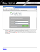
13. Navigate to Device Management-> IGSP, Select IGMP Snooping tab. Set IGSP Status to Enable, set Unknown Multicast Drop to Enable, set Multicast VLAN Status to Enable, set Multicast VLAN ID to “1”, and leave all other settings as indicated below. Click OK, and OK again.
14. Select Fast Leave tab. Click Config button. 15. Set Fast Leave to Enable, click Select All. Click OK, and OK again.
16. Make sure all the ports are set to Enable. 17. IMPORTANT: At this point all the displays should be displaying stable running video from the selected sources. If you do not have them displaying properly, than network switch is configured incorrectly.
18. Click Save Configurations on the left bottom corner. New screen will appear. Click Save under Save Current Settings, than OK and OK again. 19. IMPORTANT: Now you can connect back you DHCP equipment (routers, servers and so on). 20. Power down Titan Networx network switch and power it up back again. Wait for the whole system to start and until you can see video on your displays.
21.
22. Rescan your components with Key Digital KD-IP120 Key Digital Management Software and make sure HDMI video switch is functional. 23. At this point your Titan Networx network switch is set and ready to use.
Niveo NGSME24TH-AV Network Setup Guide for KD-IP822, KD-IP922, KD-IP1022, KD-IP1080 1. Set up the computer to connect to the switch. The best method is to set a static IP address for the computer’s ethernet adapter and directly wire into the switch. The Default IP address of this switch is 192.168.2.1 2. Once wired in, connect to the network switch via web browser. When prompted, log in with the default credentials. a. The username and password are both “admin”.
3. After connecting to the switch, it is recommended to reset it to factory defaults. a. The path for this is Maintenance -> Factory Defaults. b. Note that resetting the switch to Factory Defaults does not change the IP settings of the switch.
4. After setting factory defaults, adjust the switch to use the desired subnet. In our case we use the IP address 192.168.1.251 – as this fits the default subnet of the KD-IP922 system. Ensure the DHCP client is disabled as well. Set the Router IR address to that of the router in the network. a. The path is: Configuration -> System -> IP b. After making the adjustment, the switch will automatically move to the new IP address. The computer may lose connection to the switch at this time.
6. Enable IGMP Snooping. Check “Snooping Enabled” and verify that “Fast Leave” is also enabled. Uncheck “Unregister IPMCv4 Flooding enabled” a. The path is: Configuration -> IPMC -> IGMP -> Basic Configuration 7. Create an IGMP VLAN. The ID should be set to 1. Force IGMPV2 compatibility for this VLAN. Ensure the configuration is as below: a. The path is: Configuration -> IPMC -> IGMP -> VLAN Configuration 8. Reboot the network switch and verify that the settings are correct.
WiFi Router Setup It is required to set your WiFi router to filter multicast (aka filter broadcast) to ensure that your router is not overwhelmed by the data broadcast from Enterprise AV units on the network.