
Instruction Manual


3
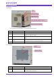
2. Explanation of each part
(1) Rear Panel
The cross mark of the photograph is the center position of the mirror
No. Name Description
1 LED Lights up when the power to the device is turned on.
2 Power switch This switch turns on / off power. Pressing "┃
" side pushes it ON,
pushing "○" side turns it OFF.
3 USB connector
Connects to the measuring computer Connector for inserting the USB
cable.
4 Synchronization signal
for
camera
0 V is output while image synch
ronization signal data of 4 cameras is
being acquired, and 3.3 V is output for the others.
5 DC 12 V power connector This is a 3 pin connector that connects DC 12 V AC adapter.
(2) Front Panel
No. Name Description
1 Handle Used for moving the movable hand tool.
2 Radome surface
It is a resin cover that covers the transmission direction surface of
the radome surface radio wave.
LED
Power switch
USB connector
Synchronization signal for camera
DC 12 V power connector
Handle
Radome surface