
Owner's manual


C:\Documents and Settings\rChijimatsu\デスクトップ\AutoIDNavigator-E\modori\soft_ch02-02.fm
2-4
OUTLINE OF AutoID Navigator
2
2-2
Names and Functions of Screen Parts
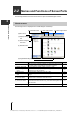
The following describes the names and functions of parts in AutoID Navigator screens.
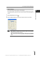
About screens
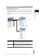
The following screen is displayed when AutoID Navigator is started up.
(1)Menu icons
(2) Display settings
tab
(3) Select configura-
tion menu
(4) Selection area
(5) Registration/setting area
(6) "Terminal" button
(8) "View image" button(7) "Test mode" button
Name Functions
See Page
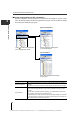
(1) Menu icons
These icons are for managing (creating new, saving and reading) project
files, setting options, and updating the connection to devices.
2-9
(2) Display settings tab This tab switches the display between "Project" or "Unit". 2-5
(3) Select configuration
menu
This menu switches display of the project display area between "system
configuration" and "file constitution".
2-6
(4) Selection area This area displays details that can be set on tabs. 2-6
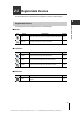
(5) Registration/setting
area
This area changes the selection of devices to register and the device
settings.
2-7
(6) "Terminal" button
This button sends commands to the connected device, and displays the
terminal screen for verification of data that is read.
6-2
(7) "Test mode" button
This button displays the test mode screen for testing the communication
status between the head and the IC tag, code reader reading status and
other information.
6-3
(8) "View image" button This button is used to obtain images with the SR-500 Series. 6-4