
User guide

Power Supply BL-U1
84
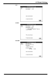
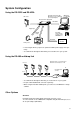
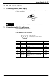
Prepare the BL series for connection to the BL-U1 by soldering a D-sub 9-pin con-
nector to the BL series cable. Then connect the cable to READER port of the BL-
U1.
Prepare the D-sub 9-pin connector and its connector case separately.
Take special care when soldering pin 5 (GND) and pin 9 (+5VDC). A wrong con-
nection will damage the unit.
Do not use a power cable over 2 meters long. A long power cable can cause a
drop in voltage, preventing the BL series from starting up properly.
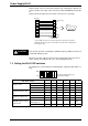
1.3
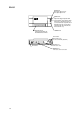
Setting the BL-U1 DIP switches
According to the selected interface and timing input, change the DIP switch set-
tings.
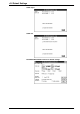
Shield
Yellow
Blown
Purple
White
Black
Gray
BL series
1
2
-
3
5
6
4
7
Connector case
TIM
RD
SD
OK
GND
NG
RS
Pink
Blue
Red
8
9
CS
+5VDC
D-sub 9-pin (female)
#4-40 screw
READER port
BL-U1
Use a metallic connector case for the D-sub 9-pin connector and connect the
shielded line to the connector case. This allows connection to the earth ground of
the AC power cable.
CAUTION
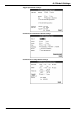
OFF
ON
123456
The switch settings at left are the
factory default settings.
DIP switch setting
1 2 3 4 5 6
Interface select
RS-232C ON OFF OFF
RS-422A OFF ON OFF
RS-485 multidrop OFF OFF ON
RS-422A terminator
(terminal resistance 100
Ω
)
OFF OFF
ON ON
RS-485 terminator
(terminal resistance 100
Ω
)
OFF OFF
ON ON
READER port CS control
method select
Reflect ON/OFF of CS
at RS-232C port
OFF
Always ON ON