360GB High-speed, High-capacity Machine Vision System CV-X Series Easy Setup Guide Control/Communication PLC-Link (YASKAWA MP Series)
Contents Easy Setup Guide: Control/Communication PLC-Link (YASKAWA MP Series) 1. Establishing the PLC-Link (Ethernet PLC-Link) Page 3 2. Establishing the PLC-Link (RS-232C PLC-Link) Page 6 3. Outputting the Measured Value/Judged Value (PLC-Link) Page 9 4. Controlling the Controller (PLC-Link) Page 12 Trademarks Product names, etc. noted in this document are registered trademarks or trademarks of their respective companies. The ™ mark and ® mark have been omitted in this manual.
1. Establishing the PLC-Link (Ethernet PLC-Link) [YASKAWA MP Series] ✎Checking the Global Settings of the CV-X Series This section describes how to establish the PLC‐Link. [Important] If it fails, establish a one-to-one connection between PLC and CV-X, and follow this manual to configure the settings and check the operations. Confirm that it operates properly, and change settings if necessary.
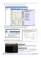
✎Configuring the MP Series Settings 1 2 3 4 Switch the E-INIT dipswitch on the MP Series unit to ON, and start up the unit. →The IP Address will be reset to 192.168.1.1 and the Port will be reset to 1024. Start MPE720 with PLC connected to the computer, and select [File] > [New project]. Then enter a file name and select a controller name to start a project. Select "Module Configuration" on the project screen. → Engineering Manager starts up. Click "00", the CPU module controller No.
On this screen, set and save the Port, IP Address, etc. Set the MP Series IP Address Save after completing the settings Local Port: The port specified in CV-X Series Global Settings Node IP Address: The CV-X Series IP Address Node Port: The port specified in CV-X Series Global Settings Connect Type: Select UDP Protocol Type: Select Extended MEMOBUS Code: Select BIN 6 Send the settings to PLC using [Online] > [Write into Controller] in MPE720.
2. Establishing the PLC-Link (RS-232C PLC-Link) [YASKAWA MP Series] ✎Checking the Global Settings of the CV-X Series This section describes how to establish the PLC‐Link. [Important] If it fails, follow this manual to configure the settings and check the operations. Confirm that it operates properly, and change settings if necessary. 1 On the "Global" menu, select [Communications & I/O] > [PLC-Link]. Configure the PLC‐Link settings.
✎Configuring the MP Series Settings 1 2 3 Start MPE720 with PLC connected to the computer, and select [File] > [New project]. Then enter a file name and select a controller name to start a project. Enter "Project name", select the "PLC model", and then press "OK". Click controller No. "01" (the number the RS232 module is connected to) on the "Module Configuration" screen in Engineering Manager. Then double-click SLOT No. 1 in "Module Details". → A detailed se ng screen for the selected module appears.
4 Use the screen below as a reference to set the communication settings. Connect Protocol: MEMOBUS Master/Slave: Slave Device Address: 1 Serial I/F: RS-232C Connect Mode: RTU Data Length: 8 Bit Parity Bit: even Stop Bit: 1 Stop Baud Rate: 115.2 K Delay: Disable Timer: Disable Auto Receipt: Enable 5 Send the settings to PLC using [Online] > [Write into Controller] in MPE720. [ 6 About the RS‐232C cable that is used to connect the CV‐X Series and the MP Series. Alter OP‐26487 (2.
3. Outputting the Measured Value/Judged Value (PLC-Link) [YASKAWA MP Series] ✎Configuring the Output Settings Set the measured values/judged values to output in "Output Settings". This section describes how to assign tool measurement values/judgment values. (In the description, the following are output: 1 : Total Status Value, 2: T100: Pattern Search. Pattern X Position Result, 3: T100: Pattern Search. Pattern XY Position Result, 4: T101: Area. Area Result, 5: T102: OCR.
✎Checking the Output Format/Flow for the Data Memory 1 Check the data memory and word count to use for the result output. Use "Result Output Address", "Result Ready Address" and "Result Ack Address" in [Global] > [Communications & I/O] > [PLC‐ Link]. - Result Output Address: Specify the first data memory for the result data output by CV‐X. * The result data is stored starting from this address by 2 words per data item (2 words per character).
3 Representative data output procedure Operations of data output procedure depending on "Result Output Settings" configured in step 1 1. When both "Acknowledge result output completion" and "Enable Handshake" are checked Follows the above procedure, and guarantees that all result data output from CV‐X is sent to PLC. However, if the PLC repeats measurement without controlling Result Ack Address (bit), the output buffer of CV‐X overflows, and trigger input becomes impossible. 2.
4. Controlling the Controller (PLC-Link) [YASKAWA MP Series] ✎Checking the Global Settings of the CV-X Series 1 On the "Global" menu, select [Communications & I/O] > [PLC-Link] to open the global "PLC-Link" settings screen. * The screen on the left shows that Mode is set to "PLC‐ Link (Ethernet)", but the settings (in the red frame) in this section (Controlling the Controller) are the same as those of "PLC‐ Link (RS‐232C)". 2 Check the setting items necessary for controller control.
✎Command Processing Flow To control the controller via PLC‐Link, use the number‐specified commands. 1 Refer to "Control/Data Output via Commands" in the user's manual to check the commands to use and the formats of the number-specified commands. Here is an example of using the PW command (command No. 24) that switches the program setting. The following must be specified to execute the PW command: Command No. (24) SD card No. (d) of the switch target program setting Setting No.
✎Command Processing Flow 2 Command execution procedure There are two methods for executing a command: "PLC Terminal" and "Polling". If "Polling" is selected, terminal control is not required but the communication for polling is required, and the command execution may be slower than "PLC Terminal". "PLC Terminal" Executes a command when the input terminal IN15 "PLC Terminal" is set.
✎Command Execution Procedure Example: Save Settings (SS Command) Here is an example of a representative command execution procedure. This section explains an example of executing the SS (Save Settings) command, which does not use a command parameter, with Command Execute Event set to "Polling". The screens with blue frames show when the "Watch" function of MPE720 is used for confirmation. 1 Check the SS (Save Settings) command operation. 1. Enter "12", the SS command No.
✎Command Execution Procedure Example: Switch Program Setting No. (PW) Here is an example of a representative command execution procedure. This section explains an example of executing the PW (Switch Program Setting No.) command, which uses a command parameter, with Command Execute Event set to "Polling". The screens with blue frames show when the "Watch" function of MPE720 is used for confirmation. 1 Check the PW (Switch Program Setting No.) command operation. 1.
✎Command Execution Procedure Example: Rewrite Judgment Conditions (DW) Here is an example of a representative command execution procedure. This section explains an example of executing the DW (Rewrite Judgment Conditions) command, which specifies numeric values as command parameters, with Command Execute Event set to "Polling". The screens with blue frames show when the "Watch" function of MPE720 is used for confirmation. 1 Check the DW (Rewrite Judgment Conditions) command operation. 1.
✎Command Execution Procedure Example: Rewrite Registered String (CW) Here is an example of a representative command execution procedure. This section explains an example of executing the CW (Rewrite Registered String) command, which specifies a string for the command parameter, with Command Execute Event set to "Polling". The screens with blue frames show when the "Watch" function of MPE720 is used for confirmation. 1 Check the CW (Rewrite Registered String) command operation. 1.
Copyright (c) 2014 KEYENCE CORPORATION. All rights reserved.