
Owner's manual
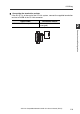


2-3 Configuring the Data Link
2-11
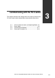
2
Connection and Configuration
- CC-Link Compatible Network Unit DL-CL1 User’s Manual (FD-S) -
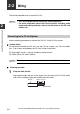
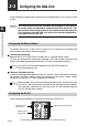
Setting the transmission rate
Set the transmission rate of the DL-CL1 to the same value as set in the CC-Link
master station.
Do this using the transmission rate setting switch on the DL-CL1.
• Default value: 0
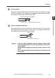
Setting the station number
Using the station address setting switch, set the station number (slave ID) assigned to
the DL-CL1.
• Default value: 01
• Setting rang
e: 0
1 to 64
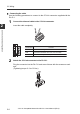
Selecting an operating mode
Using the operating mode setting switch, set the combination of the number of
stations occupied by the DL-CL1 and the extended cyclic setting. The specific data
that can be communicated using cyclic transfer varies with each operating mode.
See the section "Selecting an Operating Mode of the DL-CL1" and select the
appropriate operating mode that suits the desired function of sensor amplifiers.
• Default
value: Small-memory mode 1
• The contents of output and current value vary depending on the sensor amplifiers
to be connected.
Examples: 3-level judgment outpu t for 3-output mode; 5-level judgment output for
5-output mode. Current value: judgment value.
No. 0 1 2 3 4 5 to 9
Transmission rate (bps) 156 k 625 k 2.5 M 5 M 10 M
Cannot be set.
Switch setting
Operating mode
Station
configuration
Number of link points
RX/R Y
RW w/ RW r
Small-memory mode 1
(1-output, 1-input)
1-station, 1x
32
4
Small-memory mode 2
(3-output, 3-input)
64
8
Monitor mode 1
(5-output, 5-input, current value,
BANK change)
128
16
128
32
Full mode 1
(5-output, 5-input, current value,
BANK change, setting value change)
384
64
Others Cannot be set −
224
32
2-station, 1x
4-station, 1x
1-station, 8x
4-station, 2x
2-station, 8x
Monitor mode 2
(5-output, 5-input, current value,
BANK change)
Full mode 2
(5-output, 5-input, current value,
BANK change, setting value change)