
Manual


2-3 Configuring the Data Link
2-10
- DeviceNet Compatible Network Unit DL-DN1 User’s Manual (SK-1000) -
2
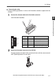
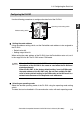
Connection and Configuration
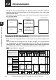
Basic mode
Use switch bits 1 and 2 to configure the basic mode.
Default value: 3-output mode
• The output content depends on the sensor amplifiers to be connected.
Examples: 3-level judgment output in 3-output mode; 5-level judgment output in 5-
output mode
• The size of the occupied memory depends on the number of amplifiers to be connected.
Extended mode
Switch bits 3 and 4 can be set to add one of the following extended functions to the
basic mode.
Default value: No extended mode
The size of the occupied memory depends on the number of amplifiers to be
connected and the setting of the basic mode.
Each switch should be set before turning on the power. If any setting
is changed while the DL-DN1 is operating, the new setting will not be
applied until the power is turned on again. (The module status indica-
tor flashes in red.)
The baud rate is set automatically to the value set on the DeviceNet master
unit.
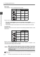
Switch setting Operating mode
Occupied memory
IN area OUT area
3-output mode 8 byte 0 byte
5-output mode 12 byte 0 byte
"3-output + current value"
mode
14 to 70 byte 0 byte
"5-output + current value"
mode
18 to 74 byte 0 byte
Switch setting Operating mode
Occupied memory
IN area OUT area
No extended mode
--
External input mode
14 to 84 byte 6 to 10 byte
"External input +
BANK change"
mode
18 to 88 byte 10 to 14 byte
"External input +
setting value change" mode
22 to 96 byte 24 to 40 byte
Point
Reference