96131E DeviceNet Compatible Network Unit DL-DN1 User’s Manual (IL) Read this manual before using the product in order to achieve maximum performance. Keep this manual in a safe place for future reference.
Introduction This manual describes the basic operations and hardware functions of the DL-DN1. Read the manual carefully to ensure safe performance and function of the DL-DN1. Keep this manual in a safe place for future reference. Ensure that the end user of this product receives this manual. Symbols The following symbols alert you to matters concerning the prevention of injury and product damage. DANGER It indicates a hazardous situation which, if not avoided, will result in death or serious injury.
Safety Precautions General Precautions • Before and while operating this product, confirm that it provides its functions and performance correctly. • Implement sufficient safety measures to prevent human and physical damages in case this product fails. • Be aware that the product functions and performance are not warranted if the product is used outside the range of stated specifications or is modified by the customer.
Safety Precautions Noise Protection If this product is installed in a location near a noise source, e.g., power source or highvoltage line, it may malfunction or fail because of noise. Use protection measures, such as using a noise filter or running the cables separately. Notes on Regulations and Standards UL Certificate This product is an UL/C-UL Listed product. • UL File No.
Safety Precautions MEMO - DeviceNet Compatible Network Unit DL-DN1 User’s Manual (IL) - 3
Relevant Manuals The manuals relevant to this document are as follows: Manuals relevant to CPU unit Example: KV-5000 user's manual PLC CPU unit DeviceNet master unit KV- DN 20 MS NS ON TE RM .
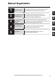
Manual Organization Before Using This chapter provides an overview of the DL-DN1 and describes its part names and functions. Connection and Configuration This chapter explains the procedures for connecting sensor amplifiers to the DL-DN1 and how to configure the data link. Communicating with the IL Series This chapter describes the configuration of the memory linked to the DeviceNet master station and provides communication time charts.
Table of Contents Safety Precautions ........................................................................................ 1 General Precautions ......................................................................... 1 Precautions for Use ........................................................................... 1 Notes on Regulations and Standards ............................................... 2 Relevant Manuals ........................................................................................
Table of Contents Basic Formats of Explicit Messaging ........................................... 3-20 Issuing a Motion Command to a Sensor Amplifier ....................... 3-22 Reading/Writing Settings or Status of a Sensor Amplifier ............ 3-23 Locking Sensor Amplifiers ............................................................ 3-25 Command Parameter List ............................................................ 3-26 Chapter 4 Specifications 4-1 4-2 4-3 Specifications ......................
Terms Used in This Document This document uses the following terms: Term Sensor Master unit Slave unit Main unit Expansion unit D-bus PGM 8 Description A sensor amplifier. A DeviceNet master unit. A DeviceNet slave unit. A sensor amplifier that has a power line and can operate alone. A sensor amplifier that does not have a power line and must be connected to a main unit. The name of KEYENCE's wiring-saving system for sensor amplifiers. Supports IL Series CMOS laser amplifier sensors and others.
Before Using This chapter provides an overview of the DL-DN1 and describes its part names and functions. 1-1 1-2 1-3 1 DL-DN1 Overview .............................................. 1-2 Checking the Package Contents ........................ 1-3 Names and Functions of Each Part....................
1-1 1 DL-DN1 Overview Overview Before Using The DL-DN1 operates as a slave unit of DeviceNet communication. Using DeviceNet communications, the sensor amplifiers and other units connected to the DL-DN1 can transmit their ON/OFF control signals and current values as communication data to a PLC or other equipment. The DL-DN1 supports DeviceNet I/O communication (polling) and explicit messaging. I/O polling enables data communication without the need of a ladder program.
1-2 Checking the Package Contents Before using the DL-DN1, make sure that the following equipment and accessories are included in the package. We have thoroughly inspected the package contents before shipment. However, in the event of defective or broken items, contact your nearest KEYENCE office.
1-3 Names and Functions of Each Part This section describes the part names and functions of the DL-DN1. 1 (1) Address setting switch (2) Operating mode setting switch (3) Module status indicator (green/red) Before Using (4) Network status indicator (green/red) DL-DN1 20-30V DC, Class2 15JN IND.CONT.EQ.
1-3 Names and Functions of Each Part Item Description (2) Operating mode set- Sets the operating mode of the DL-DN1 in the DeviceNet. ting switch The data that can be handled in remote I/O communication varies with each operating mode. Before Using Basic mode Use switch bits 1 and 2 to configure the basic mode.
1-3 Names and Functions of Each Part Item Description (3) Module status indicator (4) Network status indicator (5) Sensor communication indicator 1 Before Using (6) Sensor amplifier connector (for DIN rail mounting) (7) Sensor amplifier connector (for panel mounting/large display) When normal: Lit in green For details, see "Troubleshooting" (page 5-3). Indicates the status of communication between the DLDN1 and sensor amplifiers.
Connection and Configuration This chapter explains the procedures for connecting sensor amplifiers to the DL-DN1 and how to configure the data link. 2-1 2-2 2-3 2 Installation and Connection to Sensor Amplifiers........ 2-2 Wiring ................................................................. 2-7 Configuring the Data Link.................................
2-1 Installation and Connection to Sensor Amplifiers This section provides the procedures for installing the DL-DN1 and connecting to sensor amplifiers. 2 The DL-DN1 can be connected with the expansion units of sensor amplifiers which support D-bus. ("D-bus" is the name of KEYENCE's wiring-saving system for sensor amplifiers.) How many sensor amplifiers can be connected depends on the sensor amplifiers or units to be connected.
2-1 Installation and Connection to Sensor Amplifiers For panel mounting type ID number Sensor amplifier 01 Main unit 02 Expansion unit 2 ... Expansion unit DL-DN1 Expansion unit 08 Point • Since ID numbers are assigned automatically, changing the number of sensor amplifiers or their connection sequence may require modification of the control program. In addition, some units are restricted in their connection sequence (e.g., a unit that must be the last connection).
2-1 Installation and Connection to Sensor Amplifiers 2 2 To remove the DL-DN1, raise the main unit in the direction of arrow (3) while pushing it the direction of arrow (1). Procedures for connecting to sensor amplifiers The DeviceNet compatible communication unit DL-DN1 must be connected to sensor amplifiers before it can function. The connecting procedure varies with the mounting type of the sensor amplifiers to be connected.
2-1 Installation and Connection to Sensor Amplifiers Make sure that the sensor amplifier connector (for DIN rail mounting type) is not askew on the side face of the DeviceNet compatible communication unit, DL-DN1, as shown below. If the connector is askew, the DLDN1 may become damaged when connected to the sensor amplifier.
2-1 Installation and Connection to Sensor Amplifiers ● Connecting to sensor amplifiers (panel mounting type) 1 Connect the optional expansion cable (OP-35361) between the sensor amplifier and the DeviceNet compatible communication unit, DL-DN1. 2 Connection and Configuration Peel off the protective sticker. Expansion cable (300 mm long) NOTICE 2 • Turn off the power and connect the expansion cable securely.
2-2 Wiring This section describes how to wire the DL-DN1. Refer also to the DeviceNet Installation Manual published by ODVA. Point Turn off the power before wiring. 2 Use the following procedure to connect the DL-DN1 to the DeviceNet. Recommended cables For connection between the DL-DN1 and the DeviceNet, use a dedicated DeviceNet cable conforming to the DeviceNet specifications or a dedicated flat cable. Point Do not use non-dedicated cables, as this may inhibit proper communication.
2-2 Wiring 2 Install a shrinkable tube. Cover the exposed sheathed conductors and the sheath using a shrinkable tube approximately 40 mm long. Sheath Approx. 40mm 2 Connection and Configuration Shrinkable tube 3 Strip the sheathed conductors. Strip approximately 10 mm of sheath from the end of each conductor. Sheathed conductor Approx. 10mm Point 2-8 • If you are using solderless terminals, perform cable wiring/ trimming appropriately to suit the specifications of the particular terminals.
2-2 Wiring Connecting the cable Use the following procedures to wire to the DeviceNet connector supplied with the DLDN1. 1 Connect the trimmed cable to the DeviceNet connector. 2 Insert the cable completely. Connection and Configuration Wire color Signal name Function Black Black Blue Blue CAN_L Communication signal (Low) Bare wire SHIELD Connects the shield of the DeviceNet cable. White CAN_H Communication signal (High) Red V+ Connects 24 VDC of the communication power supply.
2-3 Configuring the Data Link Use the following procedure to connect the DL-DN1 to the DeviceNet system. Point 2 This manual covers only the functions and settings of a DeviceNet master unit which are required for communication with the DL-DN1. For the functions and settings related to the communication between the DeviceNet master unit and CPU unit, refer to the manuals shipped with your master unit or CPU unit.
2-3 Configuring the Data Link Configuring the DL-DN1 Use the following procedures to configure the data link of the DL-DN1. Operating mode setting switch Setting the node address Using the address setting switch, set the DeviceNet node address to be assigned to the DL-DN1. • Default value: 63 • Setting range: 00 to 63 When setting the node address of the DL-DN1 from the DeviceNet master unit, set it in the range of 64 to 99. The DL-DN1 enters PGM mode.
2-3 Configuring the Data Link Basic mode Use switch bits 1 and 2 to configure the basic mode. Switch setting 2 Operating mode Occupied memory IN area OUT area 3-output mode 8 byte 0 byte 5-output mode 12 byte 0 byte Connection and Configuration "3-output + current value" 14 to 70 byte mode 0 byte "5-output + current value" 18 to 74 byte mode 0 byte Default value: 3-output mode • The output content depends on the sensor amplifiers to be connected.
Communicating with the IL Series This chapter describes the configuration of the memory linked to the DeviceNet master unit and provides communication time charts. 3-1 3-2 3-3 3 Overview of DeviceNet Communication ............. 3-2 I/O Communication............................................. 3-4 Explicit Messaging............................................
3-1 Overview of DeviceNet Communication The DL-DN1 operates as a slave unit of a DeviceNet system, with support for I/O communication (polling) and explicit messaging. This section outlines the type of data that the DL-DN1 can communicate using DeviceNet and how it is communicated. Data Communicated Using DeviceNet The master unit of the DeviceNet system and the DL-DN1 are linked as shown below.
3-1 Overview of DeviceNet Communication Overview of Communication Methods The master unit of the DeviceNet system can use the following functions: Communication methods Function of sensor amplifier I/O communication p. 3-4 Explicit messaging p.
3-2 I/O Communication The device map varies depending on the operating mode of the DL-DN1. Select an operating mode suited for the functions of the sensor amplifiers to be used, before accessing each device. The memory in the DeviceNet master unit is linked to the buffer memory in the DLDN1 as shown below. DeviceNet master unit DL-DN1 Sensor amplifier Output data IN area 3 I/O communication Data here will be reflected in the master unit.
3-2 I/O Communication Configuring the Operating Mode Setting Switch Configure the operating mode setting switch to suit the operating mode to be used.
3-2 I/O Communication "3-output + current value" mode No extended mode Yes - - - 3-input - Yes Yes Yes BANK change - - Yes - Setting value rewrite - - - Yes 3-output + monitor Area 3 Number of sensor amplifiers IN OUT IN OUT IN OUT IN Communicating with the IL Series 1 14 20 24 28 2 18 24 28 32 3 22 28 32 36 4 26 32 36 5 30 6 34 40 44 48 7 38 44 48 52 8 42 48 0 6 36 40 10 40 OUT 24 44 56 52(bytes) 5-output mode 5-output No extend
3-2 I/O Communication Device Maps The device map varies depending on the operating mode of the DL-DN1. Access each device in a manner suitable for the selected operating mode. "Status" (page 3-7) "Output" (page 3-8) "Comparator value (P.V.
3-2 I/O Communication Error information list Error ID No. Error code (HEX) Description Communicating with the IL Series nnh (01h to 0Fh) Initialization error Error encountered during initial- Check the number of conization. nected sensor amplifiers and the connection to the sensor amplifiers, and then turn off the power and back on. If the error cannot be recovered, contact your nearest sales office. 04h Mixed connection error A foreign sensor amplifier (i.e.
3-2 I/O Communication IN area Device (DEC) Name n+1 HIGH n+2 LOW n+3 GO Bit 7 Bit 6 ... Bit 1 Bit 15 Bit 14 ... Bit 9 Bit 0 Bit 8 ID08 ID07 ... ID02 ID01 Reserved ID15 ... ID10 ID09 ID08 ID07 ... ID02 ID01 Reserved ID15 ... ID10 ID09 ID08 ID07 ... ID02 ID01 Reserved ID15 ... ID10 ID09 n: The first device number assigned to the DL-DN1 The device assignments are the same for all 3-output modes including extended modes.
3-2 I/O Communication Comparator value (P.V. value) The assigned positions for comparator values vary with different operating modes. For details of communication methods, see values) from sensor amplifiers" (page 3-17). "Reading comparator values (P.V. "3-output + current value" mode IN area 3 Device (DEC) Communicating with the IL Series Bit 7 Bit 6 ... Bit 1 Bit 15 Bit 14 ... Bit 9 Bit 8 ID08 ID07 ... ID02 ID01 Reserved ID15 ...
3-2 I/O Communication External input Sensor amplifier ID numbers 01 to 08 are assigned to bits 0 to 7, respectively. For details of communication methods, see sensor amplifier" (page 3-16). "Entering an external input into a 3-output mode OUT area Name m External input-1 request m+1 External input-2 request m+2 External input-3 request Bit 7 Bit 6 ... Bit 1 Bit 15 Bit 14 ... Bit 9 Bit 0 Bit 8 ID08 ID07 ... ID02 ID01 Reserved ID15 ... ID10 ID09 ID08 ID07 ...
3-2 I/O Communication IN area 3 Device (DEC) Name n+6 External input-1 response n+7 External input-2 response n+8 External input-3 response n+9 External input-4 response n+10 Reserved Bit 7 Bit 6 ... Bit 1 Bit 15 Bit 14 ... Bit 9 Bit 0 Bit 8 ID08 ID07 ... ID02 ID01 Reserved ID15 ... ID10 ID09 ID08 ID07 ... ID02 ID01 Reserved ID15 ... ID10 ID09 ID08 ID07 ... ID02 ID01 Reserved ID15 ... ID10 ID09 ID08 ID07 ... ID02 ID01 Reserved ID15 ...
3-2 I/O Communication 5-output mode OUT area Device (DEC) Name m+5 Request to change BANK m+6 Select BANK number Bit 7 Bit 6 ... Bit 1 Bit 15 Bit 14 ... Bit 9 Bit 0 Bit 8 ID08 ID07 ... ID02 ID01 Reserved ID15 ... ID10 ID09 Specifies a new BANK number (2-byte unsigned integer; range: 0-3). m: The first device number assigned to the DL-DN1 3 IN area Name n+11 BANK change complete n+12 BANK change error Bit 6 ... Bit 1 Bit 0 Bit 15 Bit 14 ... Bit 9 Bit 8 ID08 ID07 .
3-2 I/O Communication IN area 3 Bit 7 Bit 6 ... Bit 1 Bit 15 Bit 14 ... Bit 9 Bit 0 Bit 8 ID08 ID07 ... ID02 ID01 Reserved ID15 ... ID10 ID09 ID08 ID07 ... ID02 ID01 Reserved ID15 ... ID10 ID09 Device (DEC) Name n+7 Setting-value rewrite error n+8 HIGH setting value (BANK 0) rewrite complete n+9 LOW setting value (BANK 0) rewrite complete ID08 ID07 ... ID02 ID01 Reserved ID15 ... ID10 ID09 n+10 Shift target value (BANK 0) rewrite complete ID08 ID07 ...
3-2 I/O Communication IN area Bit 7 Bit 6 ... Bit 1 Bit0 Bit 15 Bit 14 ... Bit 9 Bit 8 Name n+11 Setting-value rewrite error n+12 HIGH setting value (BANK 0) rewrite complete ID08 ID07 ... ID02 ID01 Reserved ID15 ... ID10 ID09 n+13 LOW setting value (BANK 0) rewrite complete ID08 ID07 ... ID02 ID01 Reserved ID15 ... ID10 ID09 n+14 Shift target value (BANK 0) rewrite complete ID08 ID07 ... ID02 ID01 Reserved ID15 ...
3-2 I/O Communication Entering an external input into a sensor amplifier Available external inputs: External inputs 1 - 4 Device assignments: "External input" (page 3-11) PLC 1 0 External Input request (1) OUTarea [m+1]Bit0 1 0 External Input response (2) IN area [n+5]Bit0 3 Sensor amplifier External Input ON OFF External input 2 for ID 01 Communicating with the IL Series This example illustrates how to enter a TIMING input into the sensor amplifier of ID01.
3-2 I/O Communication Reading comparator values (P.V. values) from sensor amplifiers Comparator values (P.V. values) are read by reading the IN areas which are assigned the ID numbers of sensor amplifiers. Device assignments: "Comparator value (P.V.
3-2 I/O Communication Changing the BANK number of sensor amplifiers Device assignments: "Changing a BANK" (page 3-12) PLC Select BANK number 3 (BANK 3) 1 (BANK 1) OUT area [m+4] (1) (4) 1 Request to change BANK of ID 01 OUT area [m+3] BIT 0 0 1 Request to change BANK of ID 02 3 0 OUT area [m+3] BIT 1 Completed in changing BANK of ID 01 1 0 (2) IN area [n+7] BIT 0 Communicating with the IL Series 1 Completed in changing BANK of ID 02 0 IN area [n+7] BIT 1 BANK change error of ID 01 1 0
3-2 I/O Communication Rewriting a setting value of a sensor amplifier Available setting values: HIGH setting value (Bank0), Low setting value (Bank0), zero shift setting value (Bank0), Analog output - upper limit value (Bank0), and Analog output - lower limit value Device assignments: "Rewrite setting value" (page 3-13) The setting value to be rewritten is the values listed above.
3-3 Explicit Messaging The DeviceNet master unit can issue explicit messages to the DL-DN1 for the following purposes: "Issuing a Motion Command to a Sensor Amplifier" (page 3-22) "Reading settings or status" (page 3-23) "Reading data with decimal point" (page 3-24) "Writing settings or status" (page 3-24) "Locking Sensor Amplifiers" (page 3-25) 3 Basic Formats of Explicit Messaging Communicating with the IL Series Shown below is the basic format used when the DeviceNet master unit issues a command to
3-3 Explicit Messaging Command format Item Description Specifies the node address, in hexadecimal, of the destination (DL-DN1) of the explicit message. Node address Specifies the type of the command. Command 0Eh Service Code 10h Write settings or status 4Bh Motion command 4Ch Lock all 4Eh Read information with decimal point 3 Fixed to 0067h. The Instance ID and Attribute ID specify the ID number and parameter of the target sensor amplifier.
3-3 Explicit Messaging Item Response data Description Replies with the data that has been read out. Replies with the content of the error. Command type Lock Instruction Read Write Code Description FF00h Successfully completed. FF05h The instance ID is out of range. 3 FF08h "Instance ID: 0" is specified. FF09h Data written is out of range. Communicating with the IL Series FF0Ch Response data (Error code) Failed to execute the motion command.
3-3 Explicit Messaging Response format • When normal Number of received bytes 0002h Responder Service Code node address **h CBh Response data Responder Service Code node address **h 94h Response data (Error code) 0000h • When abnormal Number of received bytes 0002h FF**h 3 Reading/Writing Settings or Status of a Sensor Amplifier Available settings and status: See 26) and "Common command parameter list" (page 3- "Setting/status command parameters" (page 3-30).
3-3 Explicit Messaging • When abnormal Number of received bytes 0002h Response data (Error code) Responder Service Code node address **h 94h FF**h Reading data with decimal point Command format 3 Destination node address **h Service Code 4Eh Class ID Instance ID Attribute ID 0067h ****h **h Communicating with the IL Series Specifies the parameter to be read.
3-3 Explicit Messaging • When writing data of DINT type Destination node address **h Service Code Class ID 10h Instance ID 0067h ****h Attribute ID Service data **h ********h Data to be written Specifies the parameter to be written.
3-3 Explicit Messaging Error code 0Eh is returned if the DL-DN1 is connected with any sensor amplifier that does not support key lock or full key lock. (The settings of such non-supported sensor amplifiers remain unchanged.
3-3 Explicit Messaging InstID (DEC) AttrID (HEX) Name Description Attribute Data Default type value Parameter range 69 to 6B System reserved 6C 6D Error ID number Error details. If there are errors with multiple ID numbers, the error information for the Error code smallest ID number is output. 6E Warning ID number 6F Warning code Not used with the IL Series.
3-3 Explicit Messaging Command parameter list for IL series The following tables provide command parameters for the IL series. The two types of parameters are: motion command parameters and setting/status command parameters. Motion command parameters 3 Communicating with the IL Series For the communication methods using motion command parameters, see "Issuing a Motion Command to a Sensor Amplifier" (page 3-22).
3-3 Explicit Messaging InstID AttrID (DEC) (HEX) Description 73 C 74 Two-point tuning HIGH side 2nd point confirmation operation request (Determine HIGH setting value.) C 75 Two-point tuning LOW side 1st point confirmation operation request C 76 2-point tuning LOW side 2nd point confirmation operation request (Determine LOW setting value.) C 77 Calibration SET1 Confirmation operation request C 78 Calibration SET2 Confirmation operation request (Perform calibration.
3-3 Explicit Messaging 3 Communicating with the IL Series Setting/status command parameters • For the communication methods using setting/status parameters, see "Reading/Writing Settings or Status of a Sensor Amplifier" (page 3-23). • To reduce the number of writes to the EEPROM, a write command is executed 2 seconds after it is received. If another command is received within 2 seconds, the DL-DN1 waits for another 2 seconds before executing the two commands simultaneously.
3-3 Explicit Messaging InstID (DEC) AttrID (HEX) 70 Name Description Attribute Timing status Default value Parameter range R 0: During sampling 1: Not during sampling R 0: Laser emitting 1: Laser stopped 71 to Reserved 75 76 Laser emission stop status 77 Abnormal setting *8 R 0: Normal setting 1: Abnormal setting 78 External input status *20 R 0 to 15 79 EEPROM writing result *9 R 1 0: Writing 1: Normal termination 2: Abnormal termination Zero shift/Zero shift reset result *10
3-3 Explicit Messaging InstID (DEC) AttrID (HEX) 78 Nx10+2 3 Name Analog output - lower limit value (BANK 3) Description Attribute *4 *16 R/W Default value Parameter range -10.000 -99.999 to +99.
3-3 Explicit Messaging InstID (DEC) AttrID (HEX) 69 Name Description Attribute Averaging/Diff. count filter/High-pass filter Output mode 6B Reserved R/W R/W 4 Parameter range 0: 1 time 1: 2 times 2: 4 times 3: 8 times 4: 16 times 5: 32 times 6: 64 times 7: 128 times 8: 256 times 9: 512 times 10: 1024 times 11: 2048 times 12: 4098 times 13: Diff. count filter 14: High-pass filter 0 0: N.O. 1: N.C.
3-3 Explicit Messaging InstID (DEC) AttrID (HEX) Name Description Attribute Default value Parameter range R/W 0 0: Button 1: External input Save zero-shift state R/W 0 0: OFF 1: ON Mutual interference prevention function R/W 0 0: Interference prevention OFF 1: Interference prevention ON 7A Bank switching method 7B Reserved 7C 7D 7E Display digit R/W 0 0: Default 2: 0.001 3: 0.01 4: 0.
3-3 Explicit Messaging InstID (DEC) AttrID (HEX) 6F Nx10+6 *4 *5 *6 *7 *8 *9 *18 R Default value Parameter range Main unit: "" Expansion unit: "" Product name (16-byte reading) *21 Main unit: "IL-1000/1500" Expansion unit: "IL-1050/1550" The error content of the sensor amplifier can be checked by noting the ON/OFF state of each bit. OFF (0): No error; ON (1): Error More than one error may occur simultaneously. For details of each error, refer to the IL Series User's Manual.
3-3 Explicit Messaging - 3 When "zero shift status save" is ON, writing begins immediately for data category N Data No. 65 "zero shift request" and Data No. 66 "zero shift reset request". *10 The command reads the execution result of the "zero shift request" or "zero shift reset request" whichever was last issued. *11 By reading the "system parameter current state," the system parameters of the sensor amplifier can be checked.
3-3 Explicit Messaging *19 The read value of the two-digit value can be translated to a binary number, so that the ON/OFF state of each bit can be noted to know the status of judgment output and check output. Bit 0 1 2 3 Reference Judgment output N.O. mode N.C.
3-3 Explicit Messaging MEMO 3 Communicating with the IL Series 3-38 - DeviceNet Compatible Network Unit DL-DN1 User’s Manual (IL) -
Specifications This chapter describes the specifications and dimensions of the DLDN1. 4-1 4-2 4-3 4 Specifications ..................................................... 4-2 Data Processing Times ...................................... 4-3 Dimensions.........................................................
4-1 Specifications Product name Model Communication method Compliant functions DeviceNet specifications 4 Address setting Baud rate (automatically switched) 500 kbps Maximum cable 250 kbps length 125 kbps Network power supply DeviceNet compatible communication unit DL-DN1 DeviceNet compliant Remote I/O communication (polling) Explicit messaging 0 to 63 (PGM compatible) 500 kbps/250 kbps/125 kbps 100 m for thick cable; 100 m for thin cable 250 m for thick cable; 100 m for thin cable 500 m for thick cab
4-2 Data Processing Times This section describes the length of time taken from detection by a sensor(s) to data processing by PLC. DeviceNet master unit CPU unit DL-DN1 Sensor amplifier KV-DN20 MS NS ON TERM. (1) (2) (3) (4) 4 (3) Data communication time of DL-DN1 The length of time for the data output or current value to be sent from a sensor amplifier to the DL-DN1 are summarized below.
4-2 Data Processing Times Sensor amplifier with calculation function ON 4 Number of sensor amplifier units connected Output/judgment value or current value 1 2 3 4 5 6 7 8 13.7 ms 16.7 ms 22.7 ms 25.7 ms 31.7 ms 34.7 ms 40.7 ms 43.7 ms For information on (1), (2), and (4), refer to the manual of each unit.
Dimensions 29.4 《Unit: mm》 49.5 35.5 125 9.6 5.4 °m ax. 56.3 When cover is opened: 58.3 max. 37.7 2.4 ( 42.2) 4-3 4 35.4 78.2 - DeviceNet Compatible Network Unit DL-DN1 User’s Manual (IL) - Specifications 24.
4-3 Dimensions MEMO 4 Specifications 4-6 - DeviceNet Compatible Network Unit DL-DN1 User’s Manual (IL) -
Appendix 5-1 5-2 5-3 5 DeviceNet Device Profile.................................... 5-2 Troubleshooting .................................................. 5-3 Index...................................................................
5-1 DeviceNet Device Profile Device Profile Category Item DeviceNet specifications General data 5 Appendix Physical conformance data Communication data 5-2 Vendor name Vendor ID Device profile name Profile number Product catalog number Product revision Product Code Product name Maximum network power consumption Connector type Insulation of physical layer Supported LEDs MAC ID setting Default MAC ID Setting of transmission baud rate Supported transmission baud rate "Predefined Master/Slave Connectio
5-2 Troubleshooting The indicator lamps on the main unit can be checked to determine the cause of error and the corrective actions to take. LED indications during normal operation Module status indicator (green) Network status indicator (green) Sensor communication indicator (green) Module status indicator (MS) This lamp indicates whether the DL-DN1 is operating properly. LED status Red Solid Flashing Green/ Flashing red Not lit Condition Corrective action Operating properly. On standby.
5-2 Troubleshooting Network status indicator (NS) This lamp indicates whether the DL-DN1 is properly communicating with the DeviceNet. Condition Corrective action Check that the DL-DN1 is registered in the master unit. Solid Communicating properly. The DL-DN1 is connected to the network, but the communication with the master unit is not established. The DeviceNet cable was disconnected while in operation. Network error. 5 Flashing Minor network error.
5-2 Troubleshooting Sensor communication indicator This lamp indicates whether the DL-DN1 is communicating properly with sensor amplifiers. The cause of the error can be identified by reading the error code through I/O communication or explicit messaging. "Error information list" (page 3-8) LED status Condition Corrective action Not lit - DeviceNet Compatible Network Unit DL-DN1 User’s Manual (IL) - 5-5 5 Appendix Power is not supplied to the Check that the DL-DN1 is corDL-DN1.
5-3 Index This alphabetical index provides a list of terms used in this document. C N Checking the Package Contents .........1-3 Package Contents ......................1-3 Configuring the Data Link .................2-10 Configuring the DL-DN1 ...........2-11 Configuring the Master Unit ......2-10 D 5 Data Processing Times ......................4-3 DeviceNet Device Profile ....................5-2 Device Profile ............................5-2 Dimensions .......................................
5-3 Index MEMO 5 Appendix - DeviceNet Compatible Network Unit DL-DN1 User’s Manual (IL) - 5-7
Revision History Print date Revision no.
WARRANTIES AND DISCLAIMERS (1) KEYENCE warrants the Products to be free of defects in materials and workmanship for a period of one (1) year from the date of shipment. If any models or samples were shown to Buyer, such models or samples were used merely to illustrate the general type and quality of the Products and not to represent that the Products would necessarily conform to said models or samples.
Copyright (c) 2011 KEYENCE CORPORATION. All rights reserved.