
User guide

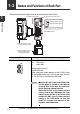

1-3 Names and Functions of Each Part
1-5
1
Before Using
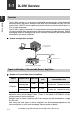
- DeviceNet Compatible Network Unit DL-DN1 User’s Manual (IL) -
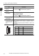
Item Description
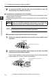
(2)Operating mode set-
ting switch
Sets the operating mode of the DL-DN1 in the DeviceNet.
The data that can be handled in remote I/O communica-
tion varies with each operating mode.
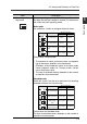
Basic mode
Use switch bits 1 and 2 to configure the basic mode.
Default value: 3-output mode
• The contents of output and current value vary depend-
ing on the sensor amplifiers to be connected.
Examples: 3-level judgment output for 3-output mode;
5-level judgment output for 5-output mode. Current
value: comparator value.
• The size of occupied memory depends on the number
of
ampl
ifiers to be connected.
Extended mode
Switch bits 3 and 4 can be set to add one of the following
extended functions to the basic mode.
Default value: No extended mode
The size of occupied memory depends on the number of
amplifiers to be connected.
Switch setting Operating mode
Occupied memory
IN area OUT area
3-output mode 8 byte 0 byte
5-output mode 12 byte 0 byte
"3-output + current value"
mode
14 to 70 byte 0 byte
"5-output + current value"
mode
18 to 74 byte 0 byte
Switch setting Operating mode
Occupied memory
IN area OUT area
No extended mode
--
External input mode
14 to 84 byte 6 to 10 byte
"External input +
BANK change"
mode
18 to 88 byte 10 to 14 byte
"External input +
setting value change" mode
22 to 96 byte 24 to 40 byte