
User guide

3-4
3
Communicating with the IL Series
- DeviceNet Compatible Network Unit DL-DN1 User’s Manual (IL) -
3-2
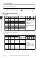
I/O Communication
The device map varies depending on the operating mode of the DL-DN1. Select an
operating mode suited for the functions of the sensor amplifiers to be used, before
accessing each device.
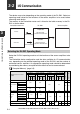
The memory in the DeviceNet master unit is linked to the buffer memory in the DL-
DN1 as shown below.
Select the DL-DN1 operating mode to suit the functions of the sensor amplifiers to be
used.
The DeviceNet device configuration and the data available for I/O communication
vary, depending on the selected operating mode of the DL-DN1 and the number of
connected sensor amplifiers. An appropriate operating mode should be determined
by considering the memory occupied and the data that can be communicated.
"Occupied Memory" (page 3-5)
Output data
Data here will be
reflected in the master unit.
Input data
Data here has been
output from the master unit.
DeviceNet master unit DL-DN1 Sensor amplifier
IN area
OUT area
I/O communication
I/O communication
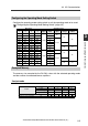
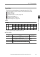
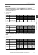
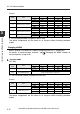
Selecting the DL-DN1 Operating Mode
Available function of sensor
amplifier
Operating mode of DL-DN1
Device maps
Communication
method
3-output
3-output + current value
5-output
5-output + current value
-
3-input
-
3-input
-
5-input
-
5-input
-
BANK
Setting
value
-
BANK
Setting
value
-
BANK
Setting
value
-
BANK
Setting
value
Read status
Ye s Ye s
Ye s Yes
3-7 3-15
Read outputs
1 - 5
HIGH
3-8 3-15
LOW
GO
Alarm output
No No
(Not used)
Read comparator value (PV value)
NoYesNo Yes 3-10 3-17
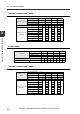
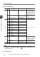
External
inputs
1 - 5
External input 1
NoYesNoYes
NoYesNo Yes 3-11 3-16
External input 2
External input 3
External input 4
No No
(Not used)
Change BANK number
No
Ye s No
No
Ye s No
No
Ye s No
No
Ye s No 3-12 3-18
Rewrite setting value NoYes NoYes NoYes No Yes 3-13 3-19