
Manual


2-2
- PROFIBUS DP Compatible Network Unit DL-PD1 User's Manual (GT-70A) -
Connection and Configuration
2
2-1
Installation and Connection to a Sensor Amplifier
This section provides the procedures for installing the DL-PD1 and connecting to sensor
amplifiers.
The DL-PD1 can be connected with the sensor amplifiers which support D-bus. ("D-bus"
is the name of KEYENCE's wiring-saving system for sensor amplifiers.) How many
sensor amplifiers can be connected depends on the sensor amplifiers to be connected.
For specific numbers of connections, refer to the manual of each sensor amplifier.
Installation and Connection to Sensor Amplifiers
Point
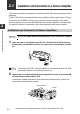
Turn off the power before connecting the DL-PD1 and sensor amplifier.
1 Align the claw on the bottom of the DL-PD1 with the DIN rail. While pushing
the amplifier in the direction of arrow (1), press down in the direction of arrow
(2).
Reference
To remove the DL-PD1, raise the amplifier in the direction of arrow (3) while
pushing the amplifier in the direction of arrow (1).
2 Repeat step 1 to install additional sensor amplifiers or input units on the DIN
rail and connect them to the DL-PD1.
If the sensor amplifier connector has an expansion protective cover, remove the
cover before connecting the amplifier.
(1)
(3)
(2)
DL-PD1
Sensor amplifier
Expansion connector