
Manual


2-1 Installation and Connection to a Sensor Amplifier
2-3
- PROFIBUS DP Compatible Network Unit DL-PD1 User's Manual (GT-70A) -
Connection and Configuration
2
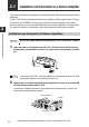
3 Mount the end units (OP-26751: a two-unit set shipped with the DL-PD1) on
both sides of the DL-PD1 and the sensor amplifier. Then, fix the end units
with the screws on the top of each end unit. (Tightening torque: 0.6 N•m or
less)
Mount the end units in the same way as the DL-PD1.
Make sure that the sensor amplifier connector (for DIN rail mounting
type) is not askew on the side face of the DL-PD1, as shown below. If
the connector is askew, the DL-PD1 may become damaged when
connected to the sensor amplifier.
Press the DL-PD1 into full engagement with the sensor amplifier. If
the DL-PD1 is not correctly connected, it may be damaged when the
power is turned on.
NOTICE
Sensor amplifier connector
DL-PD1
End unit
End unit
NOTICE