243GB PROFIBUS DP Compatible Network Unit DL-PD1 (IB) User's Manual Read this manual before use. Keep this manual in a safe place for future reference.
Introduction This manual describes the basic operations and hardware functions of the DL-PD1. Read the manual carefully to ensure safe performance and function of the DL-PD1. Keep this manual in a safe place for future reference. Ensure that the end user of this product receives this manual. Symbols The following symbols alert you to matters concerning the prevention of injury and product damage. WARNING It indicates a hazardous situation which, if not avoided, could result in death or serious injury.
Safety Precautions General Precautions WARNING • Do not use this product for the purpose to protect a human body or part of a human body. • This product is not intended for use as an explosion-proof product. Do not use this product in a hazardous location and/or potentially explosive atmosphere. CAUTION • Before and while operating this product, confirm that it provides its functions and performance correctly.
Precautions for Installation CAUTION NOTICE For safe, trouble-free operation of this product, the product must not be installed in the following locations: - Humid, dusty, or poorly ventilated. - Exposed to direct sunlight or heating source. - Exposed to corrosive or flammable gases. - Exposed directly to vibration or shock. - Exposed to water, oil, or chemical splashes. - Exposed to static electricity. If this product is installed in a location near a noise source, e.g.
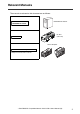
Relevant Manuals The manuals to relevant to this document are as follows: Manuals relevant to PROFIBUS DP master This manual PROFIBUS DP master DL-PD1 (This unit) Sensor Amplifier Manuals of sensor amplifier unit Example: IB series user's manual - PROFIBUS DP Compatible Network Unit DL-PD1 User's Manual (IB) - 3
Terms Used in This Document This document uses the following terms: Term Sensor amplifier 4 Explanation A sensor amplifier connected to the DL-PD1. Main unit A sensor amplifier that has a power line and can operate alone. Expansion unit A sensor amplifier that does not have a power line and must be connected to a main unit. D-bus The name of KEYENCE's wiring-saving system for sensor amplifiers. Supports IB Series thrubeam type laser detection sensors and others.
Table of Contents Introduction ......................................................................................................... 1 Safety Precautions.............................................................................................. 1 General Precautions ............................................................................... 1 Precautions for Use ................................................................................ 1 Precautions for Installation ........................
3-5 3-6 3-7 Station status ..................................................................................... 3-11 PROFIBUS DP master address ......................................................... 3-12 Manufacturer ID ................................................................................. 3-12 Identifier-related diagnosis ................................................................. 3-13 Module status.....................................................................................
Before Using This chapter provides an overview of the DL-PD1 and describes its part names and functions. 1-1 1-2 1-3 1 Characteristics of the DL-PD1............................ 1-2 Checking the Package Contents ........................ 1-4 Names of Each Part ...........................................
1-1 Characteristics of the DL-PD1 The DL-PD1 is an interface unit, which enables sensor amplifiers or input units to connect to the PROFIBUS DP. The characteristics of the DL-PD1 are shown below. 1 Slave unit of the PROFIBUS DP-V1 Before Using The following features are achieved by connecting the sensor amplifiers, which are suitable for each application, in the form of a module. • Reading out the output of the sensor amplifier.
1-1 Characteristics of the DL-PD1 Types and Number of Connectable Sensor Amplifiers Number of Connectable Sensor Amplifiers Name Main unit Expansion unit Maximum number of connectable units DIN rail mounting type IB-1000 IB-1050 4 (1 main unit, 3 expansion units) Panel mounting type IB-1500 IB-1550 4 (1 main unit, 3 expansion units) The DL-PD1 can connect to multiple sensor amplifiers (a single main unit and multiple expansion units) which support D-bus.
1-2 1 Checking the Package Contents Before using the DL-PD1, make sure that the following equipment and accessories are included in the package. We have thoroughly inspected the package contents before shipment. However, in the event of defective or broken items, contact your nearest KEYENCE office.
1-3 Names of Each Part This section describes the part names and functions of the DL-PD1. (1) Station Failure Indicator 1 (2) Bus Failure Indicator (3) Data Exchange Indicator Before Using (4) Sensor amplifier communication indicator (5) Station address setting switch (6) PROFIBUS connector (7) Sensor amplifier connector Item (1) Station Failure Indicator (2) Bus Failure Indicator (3) Data Exchange Indicator (4) Sensor amplifier communication indicator Description Normal lighting is as below.
1-3 Names of Each Part MEMO 1 Before Using 1-6 - PROFIBUS DP Compatible Network Unit DL-PD1 User's Manual (IB) -
Connection and Configuration This chapter describes installation and wiring for the DL-PD1. 2-1 2-2 2-3 2 Installation and Connection to a Sensor Amplifier ..2-2 Wiring ................................................................. 2-6 Technical data ....................................................
2-1 2 Installation and Connection to a Sensor Amplifier This section provides the procedures for installing the DL-PD1 and connecting to sensor amplifiers. The DL-PD1 can be connected with the sensor amplifiers which support D-bus. ("D-bus" is the name of KEYENCE's wiring-saving system for sensor amplifiers.) How many sensor amplifiers can be connected depends on the sensor amplifiers to be connected. For specific numbers of connections, refer to the manual of each sensor amplifier.
2-1 Installation and Connection to a Sensor Amplifier Make sure that the sensor amplifier connector (for DIN rail mounting type) is not askew on the side face of the DL-PD1, as shown below. If the connector is askew, the DL-PD1 may become damaged when connected to the sensor amplifier. Sensor amplifier connector NOTICE 3 Mount the end units (OP-26751: a two-unit set shipped with the DL-PD1) on both sides of the DL-PD1 and the sensor amplifier.
2-1 Installation and Connection to a Sensor Amplifier Connecting to sensor amplifiers (panel mounting type) 1 Connect the optional expansion cable (OP-35361) between the sensor amplifier and the DL-PD1. 2 Connection and Configuration Peel off the protective sticker. Expansion cable (300 mm long) NOTICE 2 • Turn off the power and connect the expansion cable securely. If the cable is not correctly connected, the DL-PD1 may be damaged when the power is turned on.
2-1 Installation and Connection to a Sensor Amplifier Setting the Station Address Set the station address of the DL-PD1 with the rotary switch at the top of the DL-PD1. The station address set here must be the same as the one set through the configuration software of the PROFIBUS DP. 2 Point Setting range: 01 to 99 Default value: 11 • The station address of the DL-PD1 cannot be set to 00, 100, or more. • Set the station address before the DL-PD1 is powered on.
2-2 Wiring This section describes wiring for the DL-PD1. Also refer to the Recommendation for Cabling and Assembly published by PROFIBUS International. Point Turn off the power before wiring. 2 Connection and Configuration Connecting the PROFIBUS Use the following procedure to connect the DL-PD1 to the PROFIBUS. Usable cable Use the shielded twisted pair cable, which is compliant with the PROFIBUS specifications.
2-3 Technical data Dimensions DL-PD1 29.4 2 Connection and Configuration 57.4 10 When cover is opened : 54.7 max. 34.6 1.8 (39.0) 5° m ax 43.5 35.4 (0.2) 38.1 . 94.5 Unit : mm 6 End Unit 53.8 20.8 26.4 35.4 9.
2-3 Technical data General Specifications Model 2 DL-PD1 PROFIBUS DP specifications Connection and Configuration Sensor amplifier connection specifications Device type DP-V1 Slave (D-sub 9 pin, Number of the ports: 1) Communication speed 9.6 kbit/s to 12 Mbit/s Cable length 9.6 / 19.2 / 45.45 / 93.75 kbit/s: 1200 m 187.5 kbit/s: 1000 m 500 kbit/s: 400 m 1.
Executing Communication This chapter describes the functions and detailed communication methods of PROFIBUS DP communication the DL-PD1 supports. 3-1 3-2 3-3 3-4 3-5 3-6 3-7 3 PROFIBUS communication function of DL-PD1 .... 3-2 Hardware configuration ...................................... 3-6 Parameterization ................................................ 3-8 Diagnostic Function.......................................... 3-10 Overview of PROFIBUS DP Communication ... 3-17 DP-V1 Service...................
3-1 PROFIBUS communication function of DL-PD1 This section describes the overview of the PROFIBUS DP communication functions the DL-PD1 supports. Overview 3 The DL-PD1 operates as a slave unit for PROFIBUS DP. The sensor amplifier output or comparator value can be read via the cyclic communication, and the sensor amplifier's external input ON/OFF can be controlled.
3-1 PROFIBUS communication function of DL-PD1 PROFIBUS Specifications Item GSD Revision Specifications 5 FMS No Data transmission rate Bus protocol 9.6 / 19.2 / 45.45 / 93.75 / 187.5 / 500 kbit/s 1.5 / 3 / 6 / 12 Mbit/s PROFIBUS DP Interface RS-485 Modular Device module max.15 units I/O Mode Monitor Mode PROFIBUS DEVICE ID Redundancy inputs: 10 bytes, outputs: 10 bytes inputs: max.107 bytes, outputs: max.
3-1 PROFIBUS communication function of DL-PD1 Operational flow for test operation The following settings using the PROFIBUS DP configuration software are required for the DL-PD1 to connect and communicate with the PROFIBUS DP master. 1 3 Read the GSD file. The DL-PD1 functions for PROFIBUS DP are defined by the GSD file. The GSD file can be downloaded from KEYENCE homepage. Read the downloaded GSD file using the configuration software and install it. http://www.keyence.
3-1 PROFIBUS communication function of DL-PD1 Slot number and ID number assignment When the sensor amplifiers are connected to the DL-PD1, slot numbers are assigned to each sensor amplifier. When using the acyclic communication with the DP-V1 service or diagnostic function used, the slot number is used to specify the target sensor amplifier for communication. Also, ID numbers are assigned to the control output and external input of each sensor amplifier in the connection order of sensor amplifiers.
3-2 Hardware configuration Set the hardware configuration on the configuration software of PROFIBUS DP according to the physical configuration of the DL-PD1 and sensor amplifier connected to the DL-PD1. The setting procedure differs depending on the operation mode of DL-PD1. Operation mode of DL-PD1 3 There are two types of operation modes for DL-PD1. The operation modes for DL-PD1 are switched on the hardware configuration using the configuration software of PROFIBUS DP.
3-2 Hardware configuration Input/Output size When DL-PD1 is in the monitor mode The input/output size changes according to the number of sensor amplifiers connected. Assign the "DL-PD1" and each sensor amplifier to the PROFIBUS DP system on the hardware configuration using the configuration software of PROFIBUS DP. Slot input output 0 2 bytes 1 byte 1 : 4* 7 bytes 1 byte 3 How many sensor amplifiers can be connected depends on the sensor amplifiers to be connected.
3-3 Parameterization Set parameters on the configuration software of PROFIBUS DP. Set as necessary.
3-3 Parameterization Vender parameter Unique parameters for DL-PD1 : Default value Octet Name Description - Value 11 Reserved 12 Data Format Selects data storage format when sending/receiving 2 bytes or larger data. 0: Intel (little endian) 1: Motorola (big endian) 1 (fixed) 13 Extended Diagnosis Selects whether to include information other than standard diagnosis into slave diagnosis.
3-4 Diagnostic Function Using the slave diagnostic function of PROFIBUS DP, the information of error caused on the DL-PD1 or sensor amplifier can be sent to the master via PROFIBUS DP. Slave diagnosis structure 3 The frame length of the DL-PD1 slave diagnosis is the maximum of 67 bytes. The slave diagnosis consists of 6-byte standard diagnosis, 4-byte Identifier-related diagnosis, 9byte module status and maximum of 48-byte Channel-related diagnosis.
3-4 Diagnostic Function Station status Information indicating the overview of the DL-PD1 status is stored in Octet 1 to 3. If an error occurs, each bit for Octet 1 to 3 is set. Refer to the following contents and eliminate the cause of error. Station status 1 Octet Content Solution 0 Cannot be accessed from the DP master to the DP slave.
3-4 Diagnostic Function Station status 2 Octet 2 3 bit Content 0 Set the DL-PD1 parameter again. 1 A diagnosis message is present. The DP slave does not operate until the problem is eliminated. (Static diagnosis message) 2 (1 fixed) 3 The watchdog is enabled. 4 The DP slave is in "FREEZE" state.*1 5 The DP slave is in "SYNC" state.*1 6 (0 fixed) 7 The DP slave is disabled. Executing Communication *1 This bit is updated only when another diagnosis message is updated, too.
3-4 Diagnostic Function Identifier-related diagnosis Information to identify the unit where an error occurred is stored in Octet 7 to 10. Octet Content bit Value 0 Length of the Identifier-related diagnosis 7 : 00 0100B (fixed) 5 Code for Identifier-related diagnosis 6 7 01B (fixed) 3 7 Error in Slot 7 (Sensor amplifier) 0 Error in Slot 8 (Sensor amplifier) 9 BIT corresponding to the module where an error has occurred is set.
3-4 Diagnostic Function Octet Content bit 1 2 Slot 1 module status 3 15 4 Slot 2 module status 5 6 Slot 3 module status 3 7 0 Slot 4 module status 16 1 : : 6 Executing Communication Slot 7 module status 7 0 Slot 8 module status 17 1 : : 7 0 Slot 12 module status 1 : : 6 Slot 15 module status 19 00B: Normal 01B: System error 10B: The unit on the configuration does not match the unit actually connected.
3-4 Diagnostic Function Channel-related diagnosis Information indicating the error content in 3byte per module (sensor amplifier) is stored in Octet 20 to 67. The frame length of the diagnosis changes depending on the number of module (sensor amplifier) connected (3 + 3 x [number of module (sensor amplifier) connected]). Also, Information of the module (sensor amplifier) for which the diagnostic function is set to Disable for the parameter settings is deleted from the frame and subsequent data is offset.
3-4 Diagnostic Function Octet Content bit Value 0 Identifier Number 65 Slot 15 (Sensor amplifier) Code for Channel-related diagnosis 3 : 00 1111B (fix) 5 6 7 10B (fix) 0 Channel Number 66 : 00 0000B (fix) 5 Channel Type 6 7 0 Error Type of Slot 15 : Executing Communication 4 67 11B (fix) : Input and Output "Types of error and error code" (page 4-3) 5 Channel Type : 000B (fix) 7 3-16 - PROFIBUS DP Compatible Network Unit DL-PD1 User's Manual (IB) -
3-5 Overview of PROFIBUS DP Communication The DL-PD1 enables you to read or write various settings and conditions of the sensor amplifier via PROFIBUS DP. Examples are shown below.
3-5 Overview of PROFIBUS DP Communication Device maps Monitor mode 3 In the monitor mode, the following functions can be performed.
3-5 Overview of PROFIBUS DP Communication Output Octet 0 Bit Function name Description Value External input request 1*1 Requests the external input to the sensor amplifiers. 0: OFF 1: ON 1 External input request 2*1 Requests the external input to the sensor amplifiers. 0: OFF 1: ON 2 External input request 3*1 Requests the external input to the sensor amplifiers. 0: OFF 1: ON 3 External input request 4*1 Requests the external input to the sensor amplifiers.
3-5 Overview of PROFIBUS DP Communication Sensor amplifier (Slot 1 to 4) Input Octet 3 2+7(a-1)* Executing Communication 3+7(a-1)* 4+7(a-1)* 5+7(a-1)* to 8+7(a-1)* * 3-20 Bit Function name Description Value 0 High ON/OFF of the High state of the sensor amplifiers is output. 0: OFF 1: ON 1 Low ON/OFF of the Low state of the sensor amplifiers is output. 0: OFF 1: ON 2 Go ON/OFF of the Go state of the sensor amplifiers is output.
3-5 Overview of PROFIBUS DP Communication Output Octet 0 to 4 Bit Function name Description Value External input request 1 Requests the external input to the sensor amplifiers. 0: OFF 1: ON 1 External input request 2 Requests the external input to the sensor amplifiers. 0: OFF 1: ON 2 External input request 3 Requests the external input to the sensor amplifiers. 0: OFF 1: ON 3 External input request 4 Requests the external input to the sensor amplifiers.
3-5 Overview of PROFIBUS DP Communication I/O mode In the I/O mode, the control output of the sensor amplifiers connected to the DL-PD1 can be read and external input request to the sensor amplifiers can be performed. DL-PD1 (Slot 0) Input 3 - - - - - 8 - - 9 - - Bit7 Bit6 External Requests the external input input to the sensor request 1 amplifiers. Slot 15 Slot 14 Slot 7 Slot 6 External Requests the external input input to the sensor request 2 amplifiers.
3-5 Overview of PROFIBUS DP Communication Communication Methods The following describes how the master cyclically communicates with the DL-PD1 (cyclic communication). • "Reading an output from a sensor amplifier" (page 3-23) • "Entering an external input to a sensor amplifier" (page 3-24) • "Reading comparator values (P.V.
3-5 Overview of PROFIBUS DP Communication Entering an external input to a sensor amplifier Available external inputs: PRESET, TIMING, RESET, error clear This example shows how to enter the TIMING input from Slot 1 (ID01).
3-5 Overview of PROFIBUS DP Communication Reading comparator values (P.V. values) from sensor amplifiers Comparator values (P.V. values) can be read only in the monitor mode. They cannot be read in the I/O mode. "Operation mode of DL-PD1" (page 3-6) Example of reading the comparator value (P.V.
3-6 DP-V1 Service Setting the DL-PD1 or sensor amplifier connected to DL-PD1 and reading/writing the status of them are possible via the acyclic communication of the DP-V1 service. Specify the target sensor amplifier and data for reading/writing by using the slot number and index. When the DL-PD1 operation mode is the I/O mode, the DP-V1 service can be used only when the master is Class2. When the DL-PD1 operation mode is the monitor mode, the DP-V1 service can be used with Class1 master or Class2 master.
3-6 DP-V1 Service Index (DEC) Function name Description Data type Attribute 2byte WORD R bit0-4: Error code bit5-15: 0 (Fixed) 0 to 15 32 DL-PD1 error state Stores the DL-PD1 error status. "Types of error and error code" (page 4-3) 33 Number of connectable units Stores the number of sensor amplifiers connected to the DL-PD1. 2byte INT R Error state When the sensor amplifier is in the error state, the corresponding bit is set.
3-6 DP-V1 Service Index (DEC) 3 Function name Data type 87 External input response 2 88 External input response 3 When the request reception to the "External input request 3" is complete, the corresponding bit is set.*1 2byte WORD R 89 External input response 4 When the request reception to the "External input request 4" is complete, the corresponding bit is set.
3-6 DP-V1 Service Index (DEC) Function name 175 Reserved for system 176 Number of decimal places (Current value 0, ID Number 1) : 190 Number of decimal places (Current value 0, ID Number 15) 191 Reserved for system 192 Setting error 193 194 Data type Attribute Used when reading the decimal position of ID number 01 comparator value (P.V. value). 4byte DINT R : : : 4byte DINT R When the sensor amplifier setting is abnormal, the corresponding bit is set.
3-6 DP-V1 Service IB series index (Slot 1 to 4) Attribute R: Read; W: Write; R/W: Read/Write; C: Motion command The data types are DINT (32-bit signed integer).
3-6 DP-V1 Service Index (DEC) Function name Description Data type Attribute Default value Value 34 Warning status DINT R 0: Check output OFF 1: Check output ON (in N.O.) 35 Warning function operating state DINT R 0: Check output function disabled 1: Check output function enable R Bit0: HIGH judgment output 0: OFF, 1: ON Bit1: LOW judgment output 0: OFF, 1: ON Bit2: GO judgment output 0: OFF, 1: ON Bit3: Check output 0: OFF, 1: ON *2 *20 DINT 37 Current value (P.V.
3-6 DP-V1 Service Index (DEC) 58 3 Function name Description Reference light registration result Executing Communication 59 Adjust result 60 Tuning result 61 Correction result Data type DINT Attribute R Default value Value 1 0: Executing 1: Normal termination 2: Reference light registration error 1 (Light insufficient error) 3: Reference light registration error 2 (Interfering light error) DINT R 1 0: Exciting 1: Normal termination 2: Adjust error 1 (Light insufficient error) 3: Adj
3-6 DP-V1 Service Index (DEC) Function name Description Data type Attribute Default value 105 System parameter *12 DINT R/W 0 106 Tolerance tuning setting width *16 DINT R/W 10.00 107 Calibration function 108 Measured/Logical correction target 1 109 Measured/Logical correction target 2 110 to 114 Value Main unit: 0 to 9 Expansion unit: 0 to 1 0.00 to 999.99 0: No correction (Default) 1: Measured correction 2: Logical correction DINT R/W 0 *7 DINT R/W 0.00 -999.99 to +999.
3-6 DP-V1 Service Index (DEC) 3 Executing Communication 3-34 Function name Description Data type Attribute Default value Value 138 Timing input setting DINT R/W 0 0: Level 1: Edge 139 Delay Timer DINT R/W 0 0: 1: 2: 3: 140 Timer duration DINT R/W 60 141 Hysteresis DINT R/W 0.00 0.00 to 999.99 142 Analog output scaling *17 *19 DINT R/W 0 0: Initial state 1: Free range 143 Analog output upper limit *7 *17 *19 DINT R/W +100.00 -999.99 to +999.
3-6 DP-V1 Service Index (DEC) Function name Description Data type Attribute Default value Value 157 Judgment indicator color DINT R/W 0 0: 1: 2: 3: 158 P.V.
3-6 DP-V1 Service Index (DEC) Description Data type R Main unit:="000/" Expansion unit:="050/" Attribute Default value Value 201 Product name 2 *20 DINT/ STRING 202 Product name 3 *20 DINT/ STRING R Main unit:="1500" Expansion unit:="1550" 203 Product name 4 *20 DINT/ STRING R Main unit:="" Expansion unit:="" 204 to 217 3 Function name 218 219 to 223 Reserved for system Unit Reserved for system Executing Communication *1 The error content of the sensor amplifier can be checked
3-6 DP-V1 Service Bit 0 3, 2, 1 Reference Setting details 0: 1: NPN output PNP output 000: 001: 010: 011: 100: Analog output OFF 0 to 5V -5 to +5V 1 to 5V 4 to 20mA Assume the read data is "006": Translating "6" to a binary number gives "0110". 0 110 Bit 3, 2, 1: 1 to 5 V Bit 0: NPN output Thus, the sensor amplifier from which the data was read is set to "NPN output" and "analog output 1 to 5 V".
3-6 DP-V1 Service 3 *15 These parameters are OFF only if data "0" is written and the wiring is configured to turn off external input. *16 When reading data from an amplifier unit in which the measurement mode is to "dimension mode", the read range changes to "**.***" (0.000 to 99.999). *17 A write control error results if data is rewritten to an expansion unit.
3-7 Other functions I&M The DL-PD1 supports I&M0. I&M0 I&M data Size information Description Manufacturer MANUFACTURER_ID 2bytes 01FDH ORDER_ID 20bytes (String) DL-PD1 SERIAL_NUMBER 16bytes (String) * HARDWARE_REVISION 2bytes 100 Module hardware revision SOFTWARE_REVISION 4bytes V*** Module software revision Example) V.255.255.
3-7 Other functions FREEZE/SYNC/CLEAR command The following are the DL-PD1's operations when the SYNC command or FREEZE command is notified to the DL-PD1 from PROFIBUS DP master. Operation when the FREEZE command is notified 3 The input data (e.g. sensor amplifier control output, comparator value, etc.) on the cyclic communication is fixed to the condition immediately before the FREEZE command is notified. If the FREEZE command is notified again, the condition will be updated.
Appendix 4-1 4-2 4-3 4 Troubleshooting........................................................... 4-2 Data update time......................................................... 4-5 Comparator Value Property of the Sensor Amplifier ...
4-1 Troubleshooting Indicator Specifications The communication status of PROFIBUS DP can be checked by checking the DL-PD1 indicators. LED display during Station Failure Indicator (OFF) normal operation Bus Failure Indicator (OFF) Data Exchange Indicator (green) Sensor amplifier Communication Indicator (green) 4 Appendix SF BF DE D-bus OFF OFF Green Green Red Red OFF OFF Starting up The unit enters normal state after startup operation is complete.
4-1 Troubleshooting Types of error and error code For how to read error information using a diagnosis function, refer to "Device maps" (page 3-18). Slot Solution 16 Unassigned ID error The number of sensor amplifiers increased during operation. Check the connection with the sensor amplifier. 17 Start-time Communication error Check the connection with the sensor amplifier and cycle the power.
4-1 Troubleshooting If a communication error occurs while using the DP-V1 service, the error codes below appear as error responses. Type of error 4 Error_Code 1 Error_Code 2 Description Solution Check the type of sensor amplifier connected. 0xAA 0x* Sensor busy error 0xBA 0x00 A response to the last operation command has not been returned. Check the response to the last operation command, then execute the operation command again.
4-2 Data update time The data update time for cyclic communication is shown below.
4-3 Comparator Value Property of the Sensor Amplifier Using the "Comparator value property", you can check if the sensor amplifier connected to the DL-PD1 is correctly detected. There are three types of the comparator value property - "Comparator value invalid", "Comparator value over range" and "Comparator value under range". The comparator value property is assigned as the following communication data.
4-3 Comparator Value Property of the Sensor Amplifier MEMO 4 Appendix - PROFIBUS DP Compatible Network Unit DL-PD1 User's Manual (IB) - 4-7
Revision History Print date Edition December, 2012 Official release Description - PROFIBUS DP Compatible Network Unit DL-PD1 User's Manual (IB) -
WARRANTIES AND DISCLAIMERS (1) KEYENCE warrants the Products to be free of defects in materials and workmanship for a period of one (1) year from the date of shipment. If any models or samples were shown to Buyer, such models or samples were used merely to illustrate the general type and quality of the Products and not to represent that the Products would necessarily conform to said models or samples.
2012 243GB 1122-1 243GB