
Owner's manual


4-1 Troubleshooting
4-3
- PROFIBUS DP Compatible Network Unit DL-PD1 User's Manual (IB) -
Appendix
4
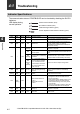
Types of error and error code
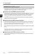
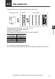
For how to read error information using a diagnosis function, refer to "Device maps"
(page 3-18).
Slot
Error code
(DEC)
Description Solution
0
(DL-PD1)
16 Unassigned ID error
The number of sensor amplifiers increased during
operation. Check the connection with the sensor
amplifier.
17 Start-time Communication error
Check the connection with the sensor amplifier
and cycle the power.
18
Unsupported Sensor Connection
error
There is connected a sensor amplifier of a model
incompatible with the DL-PD1. Connect a sensor
amplifier of a compatible model.
19 Mixed Model error
A foreign sensor amplifier (i.e., one that cannot be
intermixed) is connected. Remove the foreign
sensor amplifier.
20 Start-time Communication error
Check the connection with the sensor amplifier
and cycle the power.
21 Current Limitation error
The current limitation exceeds the allowable
range. Check the allowable range of the number of
the sensor amplifiers.
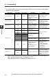
22
Communication error between
Sensors
An error exists in the communication between
sensor amplifiers. Check the connections of the
sensor amplifiers, and then turn off the power and
back on.
23 Changed Station Address error
The station address was changed during
operation. If it was not an intentional change,
check the correct station address and set.
24 to 31 Reserved for system
00 No error -
1-4
(Sensor
amplifier)
16 Overcurrent error
Refer to the IB series user's manual.
17 EEPROM error
18 Head error
19 T/R reverse connection error
20 Transmitter internal error
21 Receiver error
22 Transmitter error
23 Transmitter laser error
24 Model mismatch error
25 Ref. light quantity registration error
26 Adjust error
27 Communication error
28 to 30 Reserved for system
31 Warning info
The light quantity of the sensor head is attenuated.
• Clean the laser transmission/reception part of
the sensor head.
• Attach the receiver/transmitter of the sensor
head properly.
• Adjust the optical axis of the sensor head.
00 No error -