
User guide


1-5
- PROFIBUS DP Compatible Network Unit DL-PD1 User's Manual (IL) -
Before Using
1
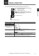
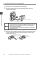
1-3 Names of Each Part
This section describes the part names and functions of the DL-PD1.
Item Description
(1) Station Failure Indicator Normal lighting is as below.
For details, refer to "Indicator Specifications" (page 4-2).
(2) Bus Failure Indicator
(3) Data Exchange Indicator
(4) Sensor amplifier
communication indicator
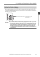
(5) Station address setting switch
Set the station address.
The place of x10: 10, the place of x1: 1
[Setting range]: 01 to 99, [Default value]: 11
The station address of the DL-PD1 cannot be set to 00, 100, or more.
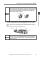
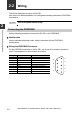
(6) PROFIBUS connector
D-sub9 pin (socket) connector compliant with the RS-485.
For details on pin layout, see "Connecting the PROFIBUS" (page 2-6).
(7) Sensor amplifier connector
Attach the sensor amplifier to this connector.
When shipped from the factory, a protection cover is installed.
(1) Station Failure Indicator
(2) Bus Failure Indicator
(3) Data Exchange Indicator
(4) Sensor amplifier communication indicator
(5) Station address setting switch
(6) PROFIBUS connector
(7) Sensor amplifier connector
OFF
OFF
Lit in green
Lit in green
Important