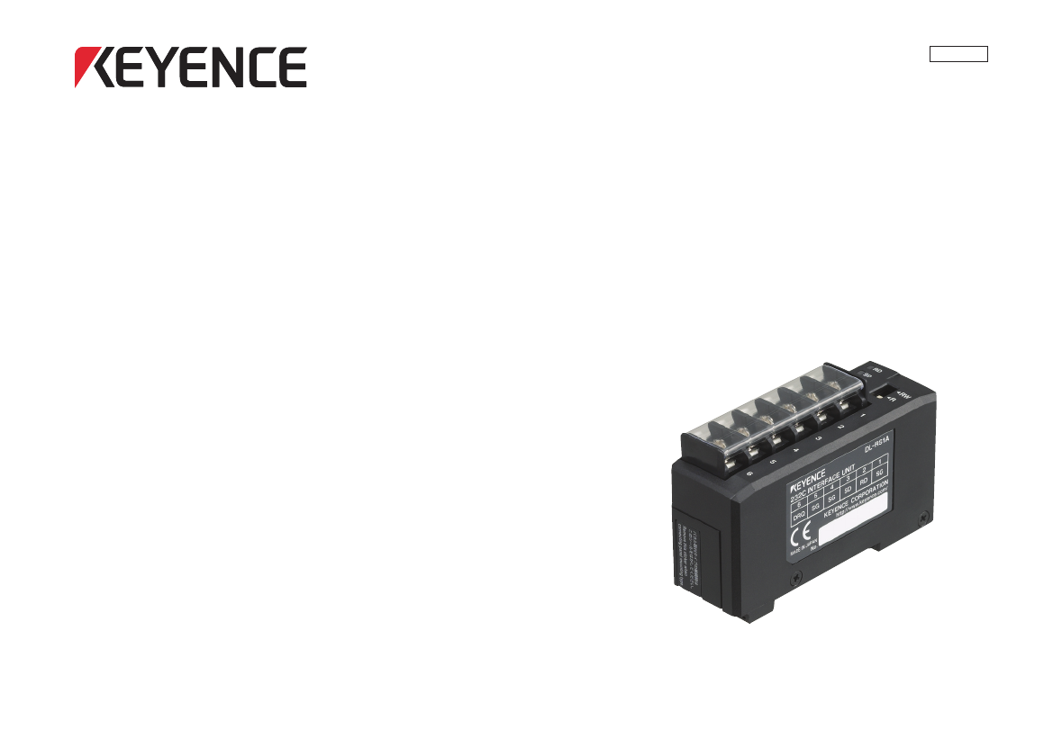
96077E RS-232C Communication Unit DL-RS1A User's Manual (FD-S Edition) Read this manual before using the system in order to achieve maximum performance. Keep this manual in a safe place for future reference.
Introduction This manual provides an overview of the RS-232C communication unit DL-RS1A and describes the functions and procedures of the unit. Be sure to read this manual carefully to ensure safe performance and function of the unit. Keep this manual in a safe place for future reference. Ensure that this manual is passed to the end user. Safety Precautions General Cautions • At startup and during operation, be sure to monitor the functions and performance of the DL-RS1A for proper operations.
Contents T5 (Response send time from DL-RS1A) .................................................................................. 15 T6 (Sensor amplifier settings change time)............................................................................... 15 Safety Precautions General Cautions Handling Errors Operating Precautions Specifications Performance Specifications ........................................................................................... 16 Communication Specifications..............
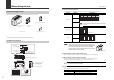
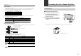
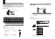
Before Using the Unit Before Using the Unit (1) Communication setup switches You can use different ON/OFF combinations to configure the communication settings. Checking the Package Contents Setting Switch No. Combination Before using the DL-RS1A, check that the following items are all included. 1 2400bit/s 4800bit/s ON 2 Baud rate ON 1 2 3 9600bit/s* ON 1 2 3 19200bit/s 38400bit/s ON ON 1 2 3 1 2 3 1 2 3 * Factory default positions are shown.
Connecting the Unit to Sensor Amplifiers Before Using the Unit This section describes how to mount a DL-RS1A and connect it to sensor amplifiers. (5) Alarm indicator This indicator lights up in red. For information on the actions you should take when an alarm occurs, refer to "Troubleshooting" (page 17). After turning on the power, the alarm indicator lights for the following amount of time, and communication cannot be performed during this time. No.
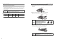
Connecting the Unit to Sensor Amplifiers Connecting the Unit to Sensor Amplifiers ■ Connecting the DL-RS1A to DIN rail mount sensor amplifiers Connecting the Unit to Sensor Amplifiers 1 NOTICE Sensor amplifier Expansion protective cover Make sure that the sensor amplifiers are turned off before connecting the RS232C communication unit DL-RS1A to them. Connecting the unit while the sensor amplifiers are turned on may damage the unit.
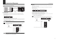
Connecting the Unit to External Devices Connecting the Unit to External Devices ■ Connection wiring Communication Terminal Block Refer to the connection wiring diagram shown below when connecting DL-RS1A to an external device such as a PC. You can connect external devices such as a PC or PLC to the communication terminal block of DL-RS1A via the communication cables.
Communication Specifications Connecting the Unit to External Devices This section provides the communication specifications of DL-RS1A and describes how to configure the unit. Sample wiring DL-RS1A (Communication terminal block) *1 *2 SG 1 RD 2 SD 3 SG SG DRQ 6 Shield*2 External device (D-sub 9-pin) Communication Specifications Black, Black/White*1 Red The following table lists the communication specifications for DL-RS1A.
Commands and Responses Commands and Responses ■ Response Overview of Commands and Responses ID No. 00 01 02 13 14 When DL-RS1A successfully receives a command from the external device, it automatically returns a response based on ASCII codes. For information on the parameters used in the response, refer to "Parameters of Commands and Responses" (page 10). Command or DRQ input Sample response structure S Main Exp. Exp. Exp. Exp.
Commands and Responses Commands and Responses ■ Error response If DL-RS1A could not receive a command from the external device or if the received command included an error, it automatically returns an "error response" based on ASCII codes. For information on the parameters used in the error response, refer to page 10. R (1) , S R (2) , Command Error No. CR LF (3) (4) S (1) Contains "ER". (2) Contains the same communication command as the received command.
Commands and Responses Commands and Responses ■ Read output states and data from all sensor amplifiers (MS command) Writing Command M S External devices such as PLC's use the following communication commands to write data to DL-RS1A.
Parameters of Commands and Responses This section describes the parameters used with various commands and responses. Parameters of Commands and Responses ■ Data numbers Specify the data number using three digits (ASCII characters). ● Read-only data Coriolis Digital Flow Sensor FD-S Series The following table lists the types of data that can only be read from FD-S Series sensor amplifiers. ■ Communication commands Point Writing read-only data results in a communication error (error number: 22).
Parameters of Commands and Responses *5 Parameters of Commands and Responses The data number “008” can be read to check the error status of the sensor amplifiers. Convert the five digit number (ASCII characters) read from the sensor amplifiers to a binary number and check the ON/OFF state of each bit to check the error contents.
Parameters of Commands and Responses Data number 052 Data name Parameters of Commands and Responses Data format*1 053 Free range analog upper limit*8 054 Keylock function ■ Control outputs Data range 0.2L 1L, 2L 8L, 20L 0.2L *** **** **.* 000 to 400 1L Free range analog lower limit*8 2L 8L 0000 to 2000 0000 to 4000 (last 1 digit 00.0 to 16.0 (last 1 digit is fixed to 0) is fixed to 0) 20L 00.0 to 40.0 0: Unlock 1: Locked * 1: 0.01 (1L(Foc) only) 2: 0.
Communication Response Time Parameters of Commands and Responses Error No. 66 67 Error name Expansion line error Write control error Problem Action Check if the separate display unit is connected. Correctly connect it by The communication could not be referring to "Connecting the Unit to established due to a problem with an Sensor Amplifiers" (page 3). Check that expansion line. the connected sensor amplifier is compatible with the DL-RS1A (refer to page 4).
Communication Response Time Communication Response Time ■ DRQ input The data read in response to a DRQ input is the buffered data that DL-RS1A periodically retrieves from the sensor amplifiers. Therefore, the latest data detected by the sensors can only be read after T2 (DL-RS1A data processing time) where DL-RS1A retrieves data from the sensor amplifiers. Time Frames of Communication Response Time This section describes the communication time frames (T2 to T6).
Communication Response Time Communication Response Time ■ T4 (DL-RS1A command processing time) ■ T5 (Response send time from DL-RS1A) The processing time varies according to the command sent from the external device. ● Read commands Communication command SR M0/MS/DRQ input Number of connected sensor amplifiers Command processing time (T4) FD-S Series 1 2 3 4 1 to 4 14 ms 15 ms 17 ms 18 ms 4 ms Important When using the SR command, 20ms will be added to the graph/table values.
Specifications Specifications Performance Specifications Dimensions The following table shows the performance specifications for DL-RS1A. Item Current consumption Number of connectable sensor amplifiers Ambient temperature Relative humidity Vibration Environmental Material Weight Accessories 22.5 Varies depending on the model* 2 communication status indicators (green), alarm indicator (red), power indicator (green) Indicators 43.8 37.
Problem Cause ASCII Code Table Action Power is not Make sure that the voltage of the power supplied to the supplied. sensor amplifier main unit is 20 to 30 VDC. DL-RS1A is not The power indicator (POWER) properly inserted to Reconnect the unit following the instructions in "Connecting does not light up. the expansion the Unit to Sensor Amplifiers" (page 3). connector of the sensor amplifier.
WARRANTY KEYENCE products are strictly factory-inspected. However, in the event of a failure, contact your nearest KEYENCE office with details of the failure. Revision History Date of printing Version January 2010 First edition Revision contents Released for each model. 1. WARRANTY PERIOD The warranty period shall be for one year from the date that the product has been delivered to the location specified by the purchaser. 2.
Copyright (c) 2010 KEYENCE CORPORATION. All rights reserved.