
Instruction Manual


3
GL-T11R-IM-E
Checking the Package Contents
GL-T11R........................................................ ×1
Instruction Manual (this document)..........×1
Cable
Point
Be sure to use the following cables for the connection between
the GL-R and the GL-T11R.
The GL-T11R does not operate when combined with other GL-R
cables.
■ GL-R Series
● Unit connection cable
● Extension cable
■ GL-S Series
● Unit connection cable
● Extension cable
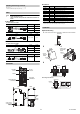
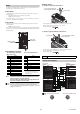
Part Names
■ Indicators
*1 When GL-R Series functions are switched using the Safety Device Configurator
setting software, indicators light up according to each function’s input status.
*2 For the GL-S Series, this indicator is fixed to being off.
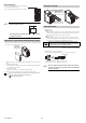
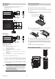
Installation
■ DIN rail Mounting
1 Push hook B down with a screwdriver to release the lock mechanism.
23
4
Removing from DIN rail
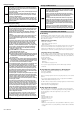
Shape Model Length
GL-RPT03PM 0.3 m
GL-RPT3PM 3 m
GL-RPT5PM 5 m
Shape Model Length
GL-RCT10PM 10 m
Shape Model Length
GL-SPT3P 3 m
GL-SPT5P 5 m
GL-SPT10P 10 m
Shape Model Length
GL-RCT10PM 10 m
45
31.5
φ5.8
φ17
(Transmitter/receiver set)
M14 connector, male
44
45
φ5.8
φ17φ17
(Transmitter/receiver set)
M14 connector, male
M14 connector, female
45
φ4
φ17
(Transmitter/receiver set)
M14 connector, male
44
45
φ5.8
φ17φ17
(Transmitter/receiver set)
M14 connector, male
M14 connector, female
POWER RESET
FSD
-
ON
WAI T
FSD
-
OFF
EDM
ERROR
O
-
RIDE
MUTE1 MUTE2
Electrical hazard
CAUTION
T R
Transmitter
connector
Indicator
Signal input/output
terminal block
Receiver
connector
Relay output
terminal block
Side Rear
SL-U2 connector
*Covered by tape
at time of
shipment.
SL-U2,
mounting
holes
DIN rail
mating
area
DIN rail
lock pin
Name Light color Description
POWER Green Lights when power is supplied
FSD ON Green Lights when FSD turns ON
FSD OFF Red Lights when FSD turns OFF
ERROR Red Lights when an error condition occurs
*1, *2
MUTE 1 Orange Lights when muting input 1 turns ON
*1
MUTE 2 Orange Lights when muting input 2 turns ON
*1
RESET Orange Lights when reset input turns ON
WAIT Orange Lights when wait input turns ON
*1
EDM Orange Lights when EDM input turns ON
O-RIDE Orange Lights when override input turns ON
*1
(Front View)
Hook B
Hook A
Hook B
* Hook A
latches on
DIN rail
DIN rail
Hook B
* Push the main
unit and latch
hook B.
[Locked state] [Unlocked state]
Hook B
Hook A
*Position hook B so that it is locked.
(Front View)
DIN rail
Hook B
Push down using
a screwdriver.