
Instruction Manual


4
GL-T11R-IM-E
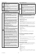
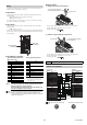
■ Screw Mounting
The two mounting holes are used to install the
GL-T11R with two M4 screws.
(Recommended tightening torque: 0.7 N•m)
Point
Always leave at least 30 mm of open space between the GL-T11R
and other equipment or walls.
* When using the SL-U2, position the SL-U2 at least 30 mm from
the edge of the cabinet.
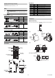
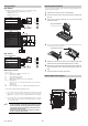
Connection to the SL-U2 Recommended Power Supply
The power can be supplied by connecting to the SL-U2 dedicated power
source via the connector on the side.
1 Remove the seal on the side of the GL-T11R that protects the connector
port.
2 [For DIN rail mounting]
• Mount the GL-T11R and the SL-U2 to the DIN rail, and slide together
to couple the connectors.
[For screw mounting]
• Couple the connector according to the figure above.
3 Slide the SL-U2 connection hook to secure it to the GL-T11R.
Reference
When not using the SL-U2, connect a power source to the power input
terminals found on the relay output terminal block.
"Wiring Example" (page 6)
Connection to the GL
Cable Specification
(1) Cable length
z GL-R Series
When using the main unit connection cable and the extension cable
together, the total length of the combined cables must be 30 m or
less for the transmitter and receiver respectively.
z GL-S Series
When using the main unit connection cable, the extension cable
and the linking cable, the total length of the combined cables must
be 20 m or less for both the transmitter and receiver.
(2) Minimum cable bending radius : 5 mm (10 mm for the part where the
connector to the GL-T11R is attached)
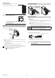
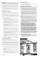
(3) Identification of connector cables
Types can be distinguished by the color of the connector end.
Cables for Transmitter: Gray connector end
Cables for Receiver : Black connector end
Point
Be sure to connect the unit connection cable for the receiver to
the GL receiver and the unit connection cable for the transmitter
to the GL transmitter.
37
124
2-φ4.2 (mounting hole)
30mm
30mm
30mm
GL-T11R
*Install while
being careful of
the connectors
DANGER
Cables must be within the lengths specified. Failure to follow
this specification may cause improper operation of the safety
functions and may cause a dangerous situation.
Receiver Connector (black)
Transmitter Connector (grey)
Receiver cable
(Black connector end)
Transmitter cable
(Gray connector end)
Connector end