
Instruction Manual


5
GL-T11R-IM-E
Wiring
Under factory default settings, shorting bars are connected between ter-
minals 8 and 9, and terminals 10 and 11.
■ GL-R Series
The GL-R Series operates with the following settings under the factory
default settings.
• Interlock function: Not used (Auto reset mode)
• EDM function: Not used
If a setting change is not necessary, use as it is. For details of each func-
tion, refer to the "GL-R User’s Manual".
■ GL-S Series
The GL-S Series operates with the following settings under the factory
default settings.
• EDM function: Not used
Not all of the input/output functions assigned to the signal input/output ter-
minals can be used. Use the signal input/output terminals with the factory
default settings.
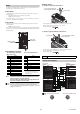
■ Input/Output assignment
Signal input/output terminal block
Relay output terminal block
(GL-R Series only)
Point
For the GL-R Series, the functions are switched to different
functions according to the settings configured with the "Safety
Device Configurator" PC setting software.
When the settings are changed, check the wiring referring to the
internal circuit diagram in the next section.
Reference
For the GL-R Series, the power source can be supplied to the muting
device or muting lamp from each 24V terminal. (The total supply
current is 95mA or less. The voltage decreases by approx. 1V from the
voltage input to GL-T11R.)
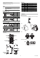
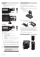
■ Wiring method
(1) Wiring the Relay Output Terminal Block
• Connectable cable : AWG24 to 12 (single wire, stranded wire)
• Connectable wire ferrule diameter: 1.3 - 2.6mm
• Cable strip length:
(2) Wiring the Signal Input/Output Terminal Block
• Connectable cable : AWG24 to 12 (single wire, stranded wire)
• Connectable wire ferrule diameter: 1.3 - 2.1mm
• Cable strip length:
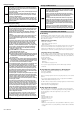
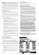
Internal circuit diagram
*1 These functions cannot be used with the GL-S.
Reference
M14 connector male pin array M14 connector female pin array
No.
Name No. Name
10 Reset input (24V) 1
FSD1
11 Reset input 2
12 Interlock selection input (24V) 3
FSD2
13 Interlock selection input 4
14 AUX output 5 FE
15 Error output 6 0V
16 Muting lamp output 7 24V (input)
*
17 Muting input 1 8 EDM input (24V)
18 Muting input 2 9 EDM input
19 Wait input
* Power supply terminal for GL-T11R.
Do not connect when the SL-U2
power source is connected to the
side of GL-T11R.
20 Override input
21 0V
POWER RESET
FSD
-
ON
WAI T
FSD
-
OFF
EDM
ERROR
O
-
RIDE
MUTE1 MUTE 2
Electrical hazard
CAUTION
Signal input/output
terminal block
Relay output
terminal block
NOTICE
Do not perform pre-tinning on the cable end.
Push in the orange projection
using the flat-head screwdriver.
Insert the cable.
10 mm
Insert the cable.
Insert the flat-head screwdriver
to the square hole.
10 mm
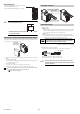
K2
K1
K1
K2
GL-R main unit
Receiver
No.
Name
1 OSSD2
2 Not used
3 OSSD1
4 Reset input
*1
5
Synchronization 1 (RS485+)
6
Synchronization 2 (RS485-)
7 24V
8 AUX output
*1
9 EDM input
10 0V
11
Interlock selection input
*1
12 FE
*1
Transmitter
No.
Name
1 Wait input
*1
2 Not used
3 Override input
*1
4 Error output
*1
5
Synchronization 1 (RS485+)
6
Synchronization 2 (RS485-)
7 24V
8
Muting lamp output
*1
9 Muting input 2
*1
10 0V
11 Muting input 1
*1
12 FE
*1
Relay unit
Relay output terminal block
No.
Name
1
FSD1
2
3
FSD2
4
5FE
*1
60V
7 24V (input)
8 EDM input (24V)
9 EDM input
Signal input/output terminal
block
*1
No.
Name
10 Reset input (24V)
11 Reset input
12
Interlock selection input (24V)
13
Interlock selection input
14 AUX output
15 Error output
16 Muting lamp output
17 Muting input 1
18 Muting input 2
19 Wait input
20 Override input
21 0V
6
10
11 12
3
4
5
21
9
8
7
6
10
12 11
9
8
7
12
3
4
5