
Instruction Manual


6
GL-T11R-IM-E
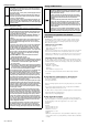
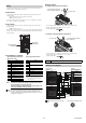
Wiring Example
■ GL-R Series
This wiring example illustrates the case of the following settings.
• Interlock function: Used (Manual reset mode)
• EDM function: Used
• Muting function: Used
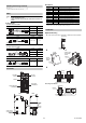
■ GL-S Series
■ Meaning of symbols
F1, F2 : Fuse
K3, K4 : External device (Magnet contactor, etc.)
S1 : Switch for reset (N.O.)
S2 : Switch for wait input (N.O.)
S3 : Switch for override (N.O.)
L1 : Muting lamp (Incandescent lamp or LED lamp)
P1, P2 : Muting device
(Photoelectric sensors with built-in amplifiers such as PZ (PNP
output), etc.)
M : 3-phase motor
PLC : For monitoring use. This is a NON-SAFETY RELATED system.
S2 and PLC are NON-SAFETY RELATED systems.
*1 No. 6 and No. 7 do not need to be wired when the SL-U2 is connected.
*2 If it is not necessary to perform error detection for K3 and K4 (when
EDM input is not used), use the shorting bar between No. 8 and No.
9.
*3 In the auto reset mode, use the shorting bar between No. 10 and No.
11. To release the error condition of a GL-R through the reset input,
connect a N.C. switch.
Point
• For the GL-R Series, the functions are switched to different
functions according to the settings configured with the "Safety
Device Configurator" PC setting software. When the settings
are changed, check the wiring referring to the internal circuit
diagram in the previous section.
• The total electric current supplied from each 24 V terminal of
the GL-T11R must be 95 mA or less.
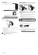
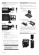
Replacing the Relay Board
The relay used for the FSD of the GL-T11R can be replaced without rewir-
ing the connection terminal.
1 Prepare the relay board for the GL-T11R (OP-87682).
2 Turn off the power to the GL-T11R and all the devices connected to the
GL-T11R.
3 Loosen the two terminal replacement screws, and remove the relay
output terminal block.
4 Loosen the two relay board replacement screws and remove the cur-
rent relay board from the GL-T11R.
5 Install the new relay board in the GL-T11R and tighten the relay board
replacement screws. (Recommended tightening torque: 0.3 N•m)
6 Attach the relay output terminal block to the relay board and tighten the
terminal replacement screws. (Recommended tightening torque: 0.3
N•m)
7 Check the operation according to the checklist.
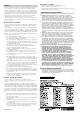
External Dimensions Diagram
K3
K3
F1
F2
K4
K3
K4
M
K4
Relay output terminal block
Name No.
FSD1
1
2
FSD2
3
4
FE 5
0V
*1
6
24V (input)
*1
7
EDM input (24V)
*2
8
EDM input
*2
9
PLC IN
P1
L1
S2
S3
P2
S1
Signal input/output terminal block
Name No.
Reset input (24V)
*3
10
Reset input
*3
11
Interlock selection input (24V) 12
Interlock selection input 13
AUX output 14
Error output 15
Muting lamp output 16
Muting input 1 17
Muting input 2 18
Wait input 19
Override input 20
0V 21
Black
Black
Blue
Brown
Brown
Blue
K3
K3
F1
F2
K4
K3
K4
M
K4
Relay output terminal block
Name No.
FSD1
1
2
FSD2
3
4
Not used 5
0V
*1
6
24V (input)
*1
7
EDM input (24V)
*2
8
EDM input
*2
9
Relay output terminal block
Relay board for the GL-T11R
2xφ4.2
(112)
35.9 49.8
3.5
83.8
(100.7) (16)
37
135
124
23
23
11
48