236GB CMOS Multi-Function Analog Laser Sensor IL Series User’s Manual Read this manual before using in order to achieve maximum performance. After reading, keep this manual in a safe place so that you can refer to it at any time.
Introduction This manual describes the basic operations and information for the IL Series. Read this manual carefully to ensure performance and function of the IL Series for safe use. Keep this manual in a safe place for future reference. Make sure this manual is provided to the end user of this device. Symbols The following symbols alert you to important messages. Be sure to read these messages carefully.
Safety Precautions General Precautions • At startup and during operation, be sure to monitor the functions and performance of this product and confirm normal operation. • We recommend that you take substantial safety measures to avoid any damage in the event that a problem occurs. • If the product is modified or used in any way other than those described in the specifications, its functions and performance cannot be guaranteed.
Item Model Wavelength FDA (CDRH) Part1040.10 IEC 60825-1 Laser Class Output Laser Class Output Description IL-S025/IL-S065/IL-065/ IL-030 IL-100/IL-300/IL-600/ IL-2000 655 nm 655 nm Class 1 Laser Product* Class 2 Laser Product* 220 μW 560 μW Class 1 Laser Product Class 2 Laser Product 220 μW 560 μW * The classification is implemented based on IEC60825-1 following the requirement of Laser Notice No.50 of FDA (CDRH).
Laser warning labels The following diagrams show the type and position of laser warning labels on to the IL Series.
IEC warning/explanatory label (CLASS 2) The IEC warning/explanatory labels are only affixed to Class 2 laser products. Use the suitable IEC warning/explanatory label included in the package of this product according to the countries and/or regions where this product is used. In this case, it can be affixed on the IEC warning/explanatory label, which has already been affixed to this product. Abnormal Conditions NOTICE If the following conditions occur, turn OFF the power immediately.
Influence of dirt Measurement errors may occur due to dust, water, oil, etc. • Blow away dirt on the transmitter and the receiver with clean air. Wipe with a soft cloth moistened with alcohol for heavy dirt. • Blow away the dirt attached to the object with clean air or wipe it off. • If dirt is floating in the measurement range, take adequate measures, such as installing a protective cover or air purge.
CSA Certificate IL series complies with the following CSA and UL standards and has been certified by CSA (Class 2252 05 / Class 2252 85). • Applicable standard: CAN/CSA C22.2 No.61010-1 UL61010-1 • Use the following power supply. CSA/UL-listed power supply that provides Class 2 output as defined in the CEC (Canadian Electrical Code) and NEC (National Electrical Code), or CSA/UL-listed power supply that has been evaluated as a Limited Power Source as defined in CAN/ CSA-C22.2 No.
IL-E 7
Table of Contents Introduction Safety Precautions.................................................................................... 1 General Precautions ................................................................................ 1 Safety Information for the IL series .......................................................... 1 Safety Precautions on Laser Products..................................................... 1 Abnormal Conditions................................................................
3-3 Initial Reset (Initialize)................................................................... 3-8 Operation for Changing the Model of Connected Head........................ 3-9 3-4 Setting the Tolerance Setting Value ........................................... 3-10 Manual Setting .................................................................................... 3-11 Automatic Setting (When other than step count filter) ........................ 3-12 Automatic Setting (When step count filter)..........
15. Display Digit .................................................................................. 4-39 16. Power Saving Function ................................................................. 4-40 17. Head Display Mode....................................................................... 4-40 18. Display Color................................................................................. 4-41 4-3 Calculation Function....................................................................
Before Use 1 This chapter describes the overview of the IL Series and the name and function of each part. IL-E 1-1 Checking the Package Contents.......................... 1-2 1-2 Part Names and Functions ...................................
1-1 1 Checking the Package Contents The following equipment and accessories are included in the package. Before using the unit, make sure that all items are included. We have thoroughly inspected the package contents before shipment. However, in the event of defective or broken items, contact your nearest KEYENCE office.
1-1 Checking the Package Contents Sensor Head IL-030 (30 mm type) IL-S025 (25 mm type) IL-S065 (65 mm type) IL-065 (65 mm type) IL-100 (100 mm type) 1 IL-300 (300 mm type) IL-600 (600 mm type) Before Use Sensor head x 1 Mounting bracket x 1 Insulating sheet x 1 Flat nut x 1 M3 x L30 screw x 2 Laser warning sticker x 1 Sensor head x 1 Mounting bracket x 1 Insulating sheet x 1 Flat nut x 1 M3 x L30 screw x 2 Sensor head x 1 Mounting bracket x 1 Insulating sheet x 1 Flat nut x 1 M4 x L35 screw x 2 Lase
1-1 Checking the Package Contents For sensor head OP-87056 (2 m) OP-87057 (5 m) OP-87058 (10 m) OP-87059 (20 m) 1 OP-87660 (2 m) OP-87661 (5 m) OP-87662 (10 m) OP-87663 (20 m) OP-84338 Before Use Sensor head cable connector x 2 Sensor head connection cable (M8 straight connector) x 1 Sensor head connection cable (M8 L-shaped connector) x 1 OP-87606 IL-2000 head mounting bracket x 1 Flat nut x 1 M5 x L60 screw x 2 1-4 IL-E
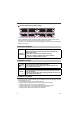
1-2 Part Names and Functions Sensor Amplifier Unit 1 DIN rail mount type (IL-1000/IL-1050) 1 Expansion unit connector* Before Use Amplifier control unit cover Amplifier control unit Expansion unit connector*2 Sensor head connector *1 When shipped from the factory, a protective cover is installed over the expansion slots. *2 It is not installed on the main unit (IL-1000).
1-2 Part Names and Functions Amplifier control unit 1 DIN rail mount type (IL-1000/IL-1050) (16) (15) (14) (1) (2) Before Use (3) (4) (5) (13) (6) (7) (8) (9) (10) (11) (12) Panel mount type (IL-1500/IL-1550) (16) (15) (14) (1) (2) (3) (4) (5) (13) (6) (7) Item (1) Main display (2) Laser warning emission indicator (3) Judgment indicator (4) Analog range indicator 1-6 (8) (9)(10) (11) (12) Description Displays the judgment value (P.V.) and each setting item.
1-2 Part Names and Functions Item (5) Bank indicator (7) Sub display indicator (8) Sub display (9) Timing input indicator (10) Zero shift indicator (11) SET button (12) MODE button (13) Arrow button (14) Alarm indicator (15) Calculation indicator (16) Hold indicator IL-E 1-7 1 Before Use (6) Zero shift button Description Displays a bank in use. "3-6 Bank Function (Registering Multiple Tolerance Setting Values)" (page 3-20) Press this button to match the internal measurement value (R.V.
1-2 Part Names and Functions Sensor Head Unit 1 IL-S025/IL-030/IL-S065/IL-065/IL-100/IL-300/IL-600/IL-2000 Before Use (1) (3) (4) (5) IL-0 30 CENTE R A. RANGE LASE (6) (2) Item (1) Laser receiver 1-8 R (3) Description Laser receiver port. The surface is covered with glass. (2) Laser transmitter Laser emission port. The surface is covered with glass. (3) Mounting section Screwed onto dedicated bracket, etc. (4) Reference distance indicator By default (normal display mode), and "17.
Installation and Connection 2 This chapter describes precautions when installing and connecting the IL Series. IL-E 2-1 Mounting and Wiring the Sensor Amplifier ........ 2-2 2-2 Connecting and Mounting the Sensor Head.......
2-1 Mounting and Wiring the Sensor Amplifier Mounting the Sensor Amplifier DIN rail mount type, main unit (IL-1000) 2 1 Align the claw at the bottom of the main body with the DIN rail. While pushing the main body in the direction of the arrow (1), slant it in the direction of the arrow (2). Installation and Connection (3) (2) 2 (1) To dismount the sensor, raise the main body in the direction of the arrow (3) while pushing the main body in the direction of the arrow (1).
2-1 Mounting and Wiring the Sensor Amplifier 1 Remove the expansion protective cover from the IL-1000 (main unit). Main unit Connector cover 2 Install the amplifiers (expansion units) on the DIN rail. 3 Push the expansion unit into the main unit connector until a clicking sound can be heard. Refer to "DIN rail mount type, main unit (IL-1000)" (page 2-2) for details about how to mount. The expansion unit installed next to the main unit is referred to as expansion unit 1.
2-1 Mounting and Wiring the Sensor Amplifier Panel mount type, main unit (IL-1500) 1 Make a hole on the panel as shown in the diagrams below. When stacking the units vertically. When stacking the units horizontally. 45 mm + 0.6 −0 2 Min. 85 mm Installation and Connection 45 mm + 0.6 −0 X mm 45 mm + 0.6 −0 • Panel thickness 1 to 6 mm • X=48 x (number of amplifiers) -3 2 3 Insert the amplifier into the panel.
2-1 Mounting and Wiring the Sensor Amplifier Panel mount type, expansion unit (IL-1550) Up to 7 expansion units can be connected to one main unit. CAU CAUTION 2 • When connecting the expansion units, make sure to initialize the connected expansion units and set the output polarity.
2-1 Mounting and Wiring the Sensor Amplifier Sensor Amplifier Wiring Connecting power/Input-output cable (only for panel mount type) 2 Connect the power/input-output cable to the panel mount type main unit and connect the input-output cable to the expansion units. To attach To remove Installation and Connection Power/Input-output cable Point 2-6 • The power/input-output cable for the main unit has 12 core wires, and the Input-output cable for the expansion units has 8.
2-1 Mounting and Wiring the Sensor Amplifier Power/Input-output cable "Output Circuit Diagram" (page 5-5) Brown *1 Blue *1 Black White Gray 10 to 30 VDC 0V 2 HIGH judgment output LOW judgment output GO judgment output Shield *2 Pink *3 Yellow *3 Pink/Purple *3 Purple *3 Analog output + Analog output GND External input 1 (Zero shift input) External input 2 (Reset input) External input 3 (Timing input) External Input 4 (Not in use) *1 IL-1050/IL-1550 (expansion units) do not have brown, blue or lig
2-2 Connecting and Mounting the Sensor Head Mounting the Sensor Head 2 Attach the sensor head using the dedicated mounting bracket. When the dedicated bracket is not used, place the included insulation sheet between the mounting surface and the sensor head as indicated in the diagram. (When the dedicated bracket is used, or when the IL-2000 is used, the insulation sheet is unnecessary.) Point The optical axis may vary by approximately ±1.5° (IL-S025/IL-S065/ IL-2000), or ±2.
2-2 Connecting and Mounting the Sensor Head Connection and Wiring Connecting the sensor head and amplifier 1 Attach the sensor head connection cables to the sensor head cable 2 (1) Align the arrow position of the connector to insert. (2) Rotate the connector screw to tighten. Installation and Connection * For the IL-2000, the direct connector will come out directly from the sensor head, so there is no arrow. Point 2 Tighten the connectors securely by hand.
2-2 Connecting and Mounting the Sensor Head 3 Attach the lock cover to the connector to secure the cable. Lock cover Locked 2 Installation and Connection Point When removing the sensor head connection cable, push the lock lever and pull it out.
2-2 Connecting and Mounting the Sensor Head Attaching the sensor head cable connector (OP-84338: optional accessory) Cut the sensor head connection cable to the required length and attach the new connector to use the sensor. The attaching method is the same for both transmitter and receiver. 1 Cut the cable to the required length and strip approx. 15 mm of insulation from the end of the cable. 2 Do not strip the core wire insulation.
2-2 Connecting and Mounting the Sensor Head MEMO 2 Installation and Connection 2-12 IL-E
Basic Operations This chapter describes basic operations and settings for the IL Series. IL-E 3-1 Operation When the Power is Turned on for the First Time....... 3-2 3-2 Operations on the Main Screens ......................... 3-3 3-3 Initial Reset (Initialize) .......................................... 3-8 3-4 Setting the Tolerance Setting Value .................. 3-10 3-5 Zero Shift Function (Shifting the Internal Measurement Value (R.V.))....
3-1 Operation When the Power is Turned on for the First Time When the amplifier is turned on for the first time after the sensor head is connected, the initial setting screen appears after a few seconds. Make the initial settings according to the following procedure. The initial setting is necessary for both the main unit and the expansion units when units are added. Once the initial setting is completed, the initial setting display will not appear when the power is turned on the second time or the after.
3-2 Operations on the Main Screens R.V. (Internal Measurement Value) and P.V. (Judgment Value) This section describes R.V. (Internal Measurement Value) displayed on the sub display (lower level) and P.V. (Judgment Value) displayed on the main display (upper level). R.V. (Internal Measurement Value) R.V. (Internal Measurement Value) is the value displayed when a target is inserted into the measurement range. * R.V. = Raw Value "3-4 Setting the Tolerance Setting Value" (page 3-10) The Judgment value (P.V.
3-2 Operations on the Main Screens Sub Display (Lower Level) The sub display can be switched with the arrow button W/X. According to the type of displayed value, the sub display indicator [R.V. / ANALOG / HI / LO / SHIFT] lights up. HOLD LASER HI [R.V.] ON GO LO ALIGNMENT 3 BANK0 1 2 3 R.V. HI CALC CHECK R.V. ANALOG LO SHIFT ZERO SHIFT TIMING (1) R.V. display screen * Displayed only for the main unit and when the analog output is used.
3-2 Operations on the Main Screens (1) R.V. display screen The internal measurement value (R.V.) is displayed. The displayed value is not held. (2) Analog output screen (Displayed when using main unit's analog output) The voltage value (unit: V) or current value (unit: mA) of the analog output is displayed.
3-2 Operations on the Main Screens Setting Operations This section explains functions operable on the main screen and functions operable after the display changes to each setting screen. Functions Operable on the Main Screen DIN rail mount type (IL-1000/IL-1050) 3 Panel mount type (IL-1500/IL-1550) Basic Operations Buttons used Main screen HOLD LASER HI GO LO ALIGNMENT BANK0 1 2 3 R.V. HI CALC CHECK ANALOG LO SHIFT ZERO SHIFT TIMING Press W or X button.
3-2 Operations on the Main Screens Available Functions from the Main Screen Main screen HOLD LASER HI GO LO ALIGNMENT BANK0 1 2 3 R.V. HI CALC CHECK ANALOG LO SHIFT ZERO SHIFT TIMING Press [MODE] button for approx. 2 seconds. 4-2 Basic Settings and Advanced Settings (page 4-4) Basic settings Basic settings such as measurement mode, response time are made. Advanced settings More advanced settings such as hold function, delay timer enable the unit to be used in wider applications.
3-3 Initial Reset (Initialize) When initial reset is performed, all settings, excluding the calibration function, are initialized. The judgment output's polarity and analog output setting can be changed with the same operation. Main screen HOLD LASER HI GO LO ALIGNMENT BANK0 1 2 3 R.V. HI CALC 1 CHECK ANALOG LO ZERO SHIFT TIMING SHIFT While pressing the [MODE] button, press the [SET] button 5 times. 3 HOLD LASER HI GO Basic Operations LO ALIGNMENT BANK0 1 2 3 R.V.
3-3 Initial Reset (Initialize) Operation for Changing the Model of Connected Head If the model of the connected head has been changed, the zero shift function and calibration function must be initialized. The following display will appear when the connected head's model is changed. 1 Connect the head of different model into the amplifier. [rESET] will appear on the main display, and [Y.or.n] will appear on the sub display. HOLD LASER HI LO ALIGNMENT BANK0 1 2 3 R.V.
3-4 Setting the Tolerance Setting Value The tolerance setting value consists of the upper limit value (HIGH side setting value) and the lower limit value (LOW side setting value). By setting these values, judgments are made in three levels: when the judgment value (P.V.) goes beyond the upper limit (HIGH judgment), when the judgment goes beyond the lower limit (LOW judgment) and when the judgment is within the acceptable range (GO judgment).
3-4 Setting the Tolerance Setting Value When setting "HIGH side setting value < LOW side setting value", the judgment output is as follows. • GO judgment output is not output regardless of the judgment value (P.V.). (When setting HIGH side setting value = LOW side setting value = judgment value (P.V.) and setting the hysteresis to 0.000, GO judgment output is turned on.) • When the judgment value (P.V.
3-4 Setting the Tolerance Setting Value 4 Press S / T button to set the LOW side setting value. IL-S025/IL-030/IL-S065/IL-065/IL-100 Item LOW side setting value Setting range -99.999 to 99.999 Default value -5.000 Setting range -999.99 to 999.99 Default value -50.00 Setting range -9999.9 to 9999.9 Default value -500.
3-4 Setting the Tolerance Setting Value 3 Press S / T button to set the tolerance setting width. Master workpiece P.V. HOLD LASER HI GO LO ALIGNMENT BANK0 1 2 3 R.V. HI ANALOG LO CALC CHECK SHIFT ZERO SHIFT TIMING Tolerance setting width IL-S025/IL-030/IL-S065/IL-065/IL-100 Item Setting width Setting range 0.000 to 99.999 Default value 0.200 IL-300/IL-600 Item Setting width Setting range 0.00 to 999.99 Default value 2.00 3 IL-2000 Item Setting range 0.0 to 9999.
3-4 Setting the Tolerance Setting Value 2 point tuning With this method, the median value of the good target and defective target is set as the tolerance setting value when there are good target and HIGH/LOW defective target. When the tuning result exceeds the setting range, the limit value of the setting range becomes the setting value. Reference Two-point tuning is not performed if the internal measurement value (R.V.) is [-----]. If performed, [no.uaL] will blink several times on the main display.
3-4 Setting the Tolerance Setting Value 5 Measure the good target again and press the [SET] button. (LOW side 1st point confirmation operation) The internal measurement value (R.V.) is imported as a good target measurement value. [Loset] is displayed on the main display (upper level). 6 Measure the LOW side defective target and press the [SET] button.
3-4 Setting the Tolerance Setting Value Automatic Setting (When step count filter) 2 point tuning 3 When there is a standard step, 2 times the value of the step will be set as HIGH (upper limit value) and half of the value of the step will be set as LOW (lower limit value) automatically.
3-4 Setting the Tolerance Setting Value 1 point tuning When there is a measurement object (herein masterwork) that can be understood from the standard step, based on the step value (P.V.) of the masterwork, 2 times the Judgment Value HIGH side setting value (upper limit) and 1/2 of the Judgment Value LOW side setting value (lower limit) can be set automatically. If the P.V. (Judgment Value) is A, HIGH = |(A) x 2|, and LOW = |(A) ÷ 2| will be the settings.
3-5 Zero Shift Function (Shifting the Internal Measurement Value (R.V.)) The internal measurement value (R.V.) is shifted (offset) to an arbitrary shift target value. The judgment value (P.V.) is shifted (offset) as well. On a main unit using the calculation function, the calculated value (CALC value) will be shifted (offset) to the shift target value instead of R.V. The following two methods can be used. • Press the [ZERO SHIFT] button (within 1 second).
3-5 Zero Shift Function (Shifting the Internal Measurement Value (R.V.)) Enabling the Zero Shift When the following operation is performed on the main screen, the zero shift indicator [ZERO SHIFT] lights up for approx. 0.5 second and the current internal measurement value (R.V.) shifts to the shift target value. • Press the zero shift button [ZERO SHIFT] (within 1 second). • Turn ON the zero shift input of external input for 20 ms or more. "13.
3-6 Bank Function (Registering Multiple Tolerance Setting Values) Using the bank function, you can register up to four patterns of specified tolerance settings. By using the bank function, each setting item registered beforehand can be switched easily.
3-7 Key Lock Function The key lock function prevents unwanted button operations during measurement. When the key lock function is active, operations other than switching the main screen and canceling the key lock function are disabled. Starting the Key Lock While pressing the [MODE] button on the main screen, press S or T button for 2 seconds or more. After [Loc] blinks on the main display (upper level) for several seconds, the main screen is restored. HOLD LO ALIGNMENT BANK0 1 2 3 R.V.
3-7 Key Lock Function MEMO 3 Basic Operations 3-22 IL-E
Setting Various Functions This chapter describes the various functions of the IL Series. IL-E 4-1 Setting Operations ................................................ 4-2 4-2 Basic Settings and Advanced Settings ............... 4-4 4-3 Calculation Function........................................... 4-42 4-4 Calibration Function ...........................................
4-1 Setting Operations Setting Operations This section explains functions operable on the main screen and functions operable after the display changes to each setting screen. Functions Available on the Main Screen DIN rail mount type (IL-1000/IL-1050) Panel mount type (IL-1500/IL-1550) 4 Setting Various Functions Buttons used Main screen HOLD LASER HI GO LO ALIGNMENT BANK0 1 2 3 R.V. HI CALC CHECK ANALOG LO SHIFT ZERO SHIFT TIMING Press W or X button.
4-1 Setting Operations Functions Available after the Display Changes to Each Setting Screen Main screen HOLD LASER HI GO LO ALIGNMENT BANK0 1 2 3 R.V. HI CALC CHECK ANALOG LO SHIFT ZERO SHIFT TIMING Press [MODE] button for approx. 2 seconds. 4-2 Basic Settings and Advanced Settings (page 4-4) Basic settings Basic settings such as measurement mode, response time.
4-2 Basic Settings and Advanced Settings List of Setting Items The following items can be set. Type Setting items 1. Measurement direction FKT 2. Sampling rate 4 52F Basic setting Setting Various Functions 3. Averaging rate, Step count filter, High-pass filter #X' 4. Alarm setting #./ 5. Output state QWV 6. Hold function *.F 7. Timing input Advanced setting VK/ 8. Delay timer F.; 9. Hysteresis *;5 10.
4-2 Basic Settings and Advanced Settings Type Setting items 11. External input KP Description Reference page Select functions of the 4 external inputs. 4-30 Set the bank switching method. 4-35 Store the settings of the state of the display based on the zero shift function into the nonvolatile memory. (EEPROM) 4-38 Set the operation of the mutual-interference prevention function. 4-38 Set the displayed digits of the judgment value (P.V.), the internal measurement value (R.V.
4-2 Basic Settings and Advanced Settings Setting Screen This section describes operations and the setting screen to modify the basic settings and the detailed setting. How to go to the setting screen Press the [MODE] button for approx. 2 seconds on the main screen. The setting screen appears.
4-2 Basic Settings and Advanced Settings Advanced settings From the advanced settings selection screen [MODE] or X 6. Hold function HOLD LASER HI GO LO BANK0 1 2 3 R.V. HI CALC CHECK *.F ANALOG LO [MODE] or X 5 * SHIFT 7.Timing input HOLD LASER HI GO LO ZERO SHIFT TIMING LO BANK0 1 2 3 R.V. HI CALC CHECK *;5 ANALOG LO [MODE] or X HOLD LO BANK0 1 2 3 R.V. HI CALC CHECK DPANALOG LO LO or X HOLD LO BANK0 1 2 3 R.V.
4-2 Basic Settings and Advanced Settings &KT 1. Measurement Direction Set whether the display value increases or decreases when the object approaches the sensor head. Measurement increase/decrease direction Default value Description The display value increases when the object approaches the sensor head. Display value 4 Normal 99.999 Setting Various Functions −99.999 c Measurement value 0 The display value decreases when the object approaches the sensor head. Display value Reverse 99.
4-2 Basic Settings and Advanced Settings 3. Averaging rate, Step count filter, High-pass filter #8' The averaging rate, the step count filter, and the high-pass filter data acquired by the sampling cycle will be set. Averaging rate The average value is the moving average. If the measured values fluctuate, stable measurements can be obtained by increasing the average count. Also, when selecting [diff], the step function, or [HPF] the High-pass filter function will be enabled. 3.
4-2 Basic Settings and Advanced Settings Step count filter Acknowledge the steps above the specified height (LOW setting value), it is the filter that does the one shot output. If the steps are acknowledged, the internal measurement value (R.V.) from the time that there is a sudden change in the + direction until that change has stopped will be the P.V. (Judgment Value). Also, the set one shot time, will make the Go decision output on, and will hold the P.V.
4-2 Basic Settings and Advanced Settings Measured value Reference R.V value (Internal Measurement Value) P.V value (Judgment Value) LOW side setting value * LOW side setting value 0 ON GO Judgment Value OFF One-shot output time * Time One-shot output time The sampling cycle is 5.5 ms when 0.33 ms, 6 ms when 5.5 ms, and 8 ms when 2 ms. 4 High-pass filter 3. Averaging rate, Press Step count filter, S / T High-pass filter button HOLD LASER HI GO LO BANK0 1 2 3 R.V.
4-2 Basic Settings and Advanced Settings Point 4 Setting Various Functions 4-12 • When the mutual-interference prevention function is enabled, the averaging of the expansion units is set equal to that of the main unit, so that the averaging setting screen for expansion units is skipped.
4-2 Basic Settings and Advanced Settings #./ 4. Alarm Setting The IL series cannot complete a measurement if it is outside the measurement range or if the light amount is excessive or insufficient. (If the measurement is impossible for a number of samples equal to the alarm number, "---" will appear.) Details of operations when measurement is impossible are set with the alarm setting. The alarm output is ON during normal measurement. It turns OFF when an alarm or error state occurs.
4-2 Basic Settings and Advanced Settings QWV 5. Output State According to the judgment value (P.V.), set the output state (N.O./N.C.) of judgment output ON/OFF and edge check output. Item Output state 4 Setting range no (Normally Open), nC (Normally Closed) Default value no There are three judgment outputs as below.
4-2 Basic Settings and Advanced Settings *.& 6. Hold Function The holding method is set for the judgment value (P.V.). Functions other than "Auto peak hold" and "Auto bottom hold" require the use of the external input (timing input). NOTICE When functions other than "Auto peak hold" and "Auto bottom hold" are set, assign external input 3 (pink/purple wire) to the timing input. "11. External Input" (page 4-30) Reference • While the judgment value (P.V.
4-2 Basic Settings and Advanced Settings Sample hold When the timing input is turned ON, the judgment value (P.V.) is held. When "Level" is set for "7. Timing Input" (page 4-23) The judgment value (P.V.) is held only while the timing input is ON. Judgment value (P.V.) Internal measurement value (R.V.)*1 Display value 4 Time Timing Input ON OFF Setting Various Functions *1 The main unit (IL-1000/IL-1500) displays the calculation value (CALC value) when the calculation function is used.
4-2 Basic Settings and Advanced Settings Peak hold The maximum value of the specified period (sampling period) is held as a judgment value (P.V.). When "Level" is set for "7. Timing Input" (page 4-23) The sampling period is from the falling edge of the timing input to the next rising edge. On the rising edge, the internal measurement value (R.V.) maximized during the sampling period is held as a judgment value. When the timing input is turned OFF, the next sampling period begins. Judgment value (P.V.
4-2 Basic Settings and Advanced Settings Bottom hold The minimum value of the specified period (sampling period) is held as a judgment value (P.V.). When "Level" is set for "7. Timing Input" (page 4-23) The sampling period is from the falling edge of the timing input to the next rising edge. On the rising edge, the internal measurement value (R.V.) minimized during the sampling period is held as a judgment value. When the timing input is turned OFF, the next sampling period begins.
4-2 Basic Settings and Advanced Settings *1 "11. External Input" (page 4-30) *2 The main unit (IL-1000/IL-1500) displays the calculation value (CALC value) when the calculation function is used. “4-3 Calculation Function” (page 4-42) *3 If the R.V. value (or CALC value) causes an alarm even once during the sampling period, the hold results will be "-----". Peak-to-peak hold The difference between the maximum value and minimum value of the specified period (sampling period) is held as a judgment value (P.
4-2 Basic Settings and Advanced Settings When "Edge" is set for "7. Timing Input" (page 4-23) The sampling period is from the rising edge of the timing input to the next rising edge of the timing input. On the rising edge, the difference between the maximum value and minimum value of the internal measurement value (R.V.) during the sampling period is held as a judgment value (P.V.). When the timing input is turned ON, the next sampling period has already begun. Display value Judgment value (P.V.
4-2 Basic Settings and Advanced Settings Auto peak hold When the internal measurement value (R.V.) goes beyond the specified trigger level, the sampling begins. When it falls below the trigger level, the sampling finishes. When the sampling finishes, the maximum internal measurement value (R.V.) during the sampling period is held as a judgment value (P.V.). The external input is not required. Judgment value (P.V.) Internal measurement value (R.V.
4-2 Basic Settings and Advanced Settings The hysteresis presents the same value as the one set for "9. Hysteresis" (page 4-26). Reference Auto bottom hold When the internal measurement value (R.V.) falls below the specified trigger level, the sampling begins. When it goes beyond the trigger level, the sampling finishes. When the sampling finishes, the internal measurement value (R.V.) minimized during the sampling period is held as a judgment value (P.V.). The external input is not required.
4-2 Basic Settings and Advanced Settings IL-2000 Item Trigger level Reference Setting range -9999.9 to 9999.9 Default value 100.0 The hysteresis presents the same value as the one set for "9. Hysteresis" (page 4-26). 6K/ 7. Timing Input The external input (timing input) operation used for "6. Hold Function" (page 4-15) is set. If "Auto peak hold" or "Auto bottom hold" is set, this item is skipped. Item Timing Input Setting range LeveL (Level), edGe (Edge) Default value LeveL &.; 8.
4-2 Basic Settings and Advanced Settings Timing chart Reference 4 • The following are the timing charts when the output state of judgment output is Normally Open (default value). ON/OFF is reversed for Normally Close. • "5. Output State" (page 4-14) • The hysteresis is not taken into account in the following timing charts. Note that the hysteresis affects the ON/OFF timing of the actual judgment output. • "9. Hysteresis" (page 4-26) Delay timer off The delay timer is not used.
4-2 Basic Settings and Advanced Settings OFF-delay timer Time required to change the GO judgment output operation from ON to OFF is delayed for specified time set on the timer. Also, time required to change the HIGH judgment output and LOW judgment output operations from OFF to ON is delayed. Judgment value (P.V.
4-2 Basic Settings and Advanced Settings *;5 9. Hysteresis The hysteresis for the tolerance setting value is set. If the judgment value (P.V.) fluctuates due to the vibration of the object, etc. and the judgment output repeats ON/OFF, increasing the hysteresis value stabilizes ON/OFF. “3-4 Setting the Tolerance Setting Value” (page 3-10) IL-S025/IL-030/IL-S065/IL-065/IL-100 Item Hysteresis 4 Setting Various Functions Setting range Default value 0.000 Setting range Default value 0.
4-2 Basic Settings and Advanced Settings #P) 10. Analog Output Scaling The analog output scaling for the judgment value (P.V.) is set. If the analog output is set to no output, this screen is skipped. “3-1 Operation When the Power is Turned on for the First Time” (page 3-2) “3-3 Initial Reset (Initialize)” (page 3-8) Analog output Default value Description Default setting Scaling is not performed. c Scaling is performed.
4-2 Basic Settings and Advanced Settings Upper limit setting screen and lower limit setting screen When set to the default state [dEFLt], the following screens will be skipped. When set to free range or bank, the upper limit setting and lower limit setting screens will appear. For free range (FrEE) 10. Analog Output Scaling HOLD LASER HI GO LO ALIGNMENT 4 BANK0 1 2 3 R.V.
4-2 Basic Settings and Advanced Settings Setting range for analog output scaling If free range or bank is selected for the analog output scaling state, the upper limit and lower limit can be set within the range shown below. IL-S025/IL-030/IL-S065/IL-065/IL-100 Item Upper limit Lower limit Setting range -99.999 to 99.999 -99.999 to 99.999 Default value 10.000 -10.000 Setting range -999.99 to 999.99 -999.99 to 999.99 Default value 100.00 -100.00 Setting range -9999.9 to 9999.9 -9999.9 to 9999.
4-2 Basic Settings and Advanced Settings KP 11. External Input You can select functions to be assigned to four external inputs (External input 1 to 4). "Power/Input-output cable" (page 2-7) External Input Description Default setting Functions for the external inputs remain the same as the factory default setting. User setting 4 Default value c Functions for the external inputs are changed from the factory default setting.
4-2 Basic Settings and Advanced Settings Zero shift input When the zero shift input is set to ON, the internal measurement value (R.V.) is shifted (offset) to an arbitrary shift target value. “3-5 Zero Shift Function (Shifting the Internal Measurement Value (R.V.))” (page 3-18) Timing chart Internal measurement value (R.V.) R.V. before shifted R.V. after shifted Max. 20 ms 4 ON Zero shift input OFF Min. 20 ms Min.
4-2 Basic Settings and Advanced Settings Timing Input When the timing input is turned ON while using the hold function, the judgment value (P.V.) is held. "6. Hold Function" (page 4-15) Timing chart z When Sample hold is set "7. Timing Input" (page 4-23) setting: "Level" Measured period 4 Hold released Measured period Sample hold Judgment value (P.V.) judgment output Setting Various Functions Max. 2 ms Max. 2 ms Max. 2 ms ON Timing Input OFF Min. 2 ms Min. 2 ms "7.
4-2 Basic Settings and Advanced Settings z When Peak hold, Bottom hold or Peak-to-peak hold is set "7. Timing Input" (page 4-23) setting: "Level" Judgment value (P.V.) judgment output Previous result No sampling Sampling period Max. 2 ms Timing Input Max. 2 ms No sampling Max. 2 ms ON OFF Min. 2 ms Min. 2 ms 4 "7. Timing Input" (page 4-23) setting: "Edge" Sampling period 2 Sampling period 1 Timing Input Previous result Sampling period 1 result Sampling period 2 result Max. 2 ms Max.
4-2 Basic Settings and Advanced Settings Bank A input/Bank B input By combining ON/OFF setting of bank A input and bank B input, you can switch the banks. “3-6 Bank Function (Registering Multiple Tolerance Setting Values)” (page 3-20) "12. Bank Switching Method" (page 4-35) Timing chart Judgment value (P.V.) judgment output 4 Bank 0 Bank 1 Bank 2 Bank 3 Max. 20 ms Bank A input ON OFF Setting Various Functions Min. 20 ms Max. 20 ms Bank B input Max. 20 ms ON OFF Max.
4-2 Basic Settings and Advanced Settings Laser emission stop input The laser emission remains interrupted while the laser emission stop input is ON. The laser emission indicator on the sensor amplifier lights off while the laser emission is stopped. "Amplifier control unit" (page 1-6) Reference Measurements are disabled while the laser emission is stopped. R.V. is determined by the alarm process.
4-2 Basic Settings and Advanced Settings Switching the bank with button operations Press the S/T button while holding down the [MODE] button on the main screen. The bank will switch, and the bank indicator [BANK0 to 3] will light according to the selected bank. BANK 0 lights Press T while holding down the [MODE] button. 4 BANK 1 lights Setting Various Functions Press T while holding down the [MODE] button.
4-2 Basic Settings and Advanced Settings Switching the bank by the external input When the Bank A input and Bank B input are set for the external inputs, the bank can be switched using the external inputs. "11. External Input" (page 4-30) "12. Bank Switching Method" (page 4-35) 1 The banks are switched with the ON/OFF combination of the bank A input and bank B input. • The bank input must be held 20 ms or longer. "11.
4-2 Basic Settings and Advanced Settings 13. Zero Shift Value Memory Function 5(V When the zero shift is performed with the external input, make the setting for the nonvolatile memory (EEPROM) to save the shifted status. When the zero shift is performed with the sensor amplifier button operation, it is saved on the nonvolatile memory (EEPROM) regardless of the setting. “3-5 Zero Shift Function (Shifting the Internal Measurement Value (R.V.
4-2 Basic Settings and Advanced Settings Point • If the data between the heads is not synchronized when using the calculation function or when the DL series is connected, disable the mutual-interference prevention function and set the main unit's sampling rate to a rate other than 0.33 ms. When the mutual-interference prevention function is enabled, or 0.33 ms is set, the timing for updating the main unit and expansion unit's internal data will not match.
4-2 Basic Settings and Advanced Settings 'EQ 16. Power Saving Function When no buttons are pressed for more than one minute, the power saving function is activated with the sensor amplifier. The power saving function is activated as soon as the setting is complete. The normal display is restored by pressing any of the buttons.
4-2 Basic Settings and Advanced Settings Near measurement center IL-S025 : 25 mm ± 0.25 mm IL-030 : 30 mm ± 0.25 mm IL-S065/IL-065 : 65 mm ± 0.5 mm IL-100 : 100 mm ± 1 mm IL-300 : 300 mm ± 7 mm IL-600 : 600 mm ± 20 mm IL-2000: 2000 mm ± 50 mm IL-030 CENTER A.RANGE LASER (1) Reference distance indicator*3 (2) Analog range indicator*3 (3) Laser radiation emission indicator %Q. 18. Display Color The LED color of the judgment indicator is set.
4-3 Calculation Function The internal measurement value (R.V.) for the "main unit" and the "expansion unit additionally installed next to the main unit (referred to as expansion unit 1)" can be calculated (addition or subtraction). If there is more than one expansion unit, the calculation function can be used between the "main unit" and the "expansion unit 1" only. There are two calculation modes for the calculation function. • Addition Mode • Subtraction Mode Point 4 Setting Various Functions 1.
4-3 Calculation Function Addition Mode In the addition mode, the added value of the internal measurement value (R.V.) for the "main unit (A)" and the "expansion unit 1 (B)" is considered as the calculation value (CALC value). Calculation value = (A’s R.V.) + (B’s R.V.) The thickness or width of a large object that cannot be measured with the measurement range of one sensor head can be measured.
4-3 Calculation Function Setting Method (Only Main Unit) Main screen HOLD LASER HI GO LO ALIGNMENT BANK0 1 2 3 R.V. HI CALC CHECK ANALOG LO SHIFT ZERO SHIFT TIMING Press [MODE] + W button 2 seconds or more at the same time 4 HOLD LASER HI GO LO ALIGNMENT BANK0 1 2 3 R.V. HI CALC CHECK %#. ANALOG LO 1 Q(( [20.CaL] is displayed on the main display (upper level). 2 Setting Various Functions [MODE] or X button HOLD LASER HI GO LO BANK0 1 2 3 R.V.
4-4 Calibration Function Setting method (Calibrating R.V.) When there is a difference between the internal measurement value (R.V.) and the actual dimension of the object, the value can be calibrated. The zero point (offset) and tilt are both corrected. Displayed value Calibration R.V. you wish to display (2) [5'V ] R.V. before calibration (2) R.V. you wish to display (1) [5'V ] 4 R.V.
4-4 Calibration Function [SEt1] R.V. value HOLD BANK0 1 2 3 R.V. HI CALC CHECK LASER HI GO LO 3 ANALOG LO SHIFT Insert workpiece A for which the measured value is known, and using the S / T buttons, set the "R.V. you wish to display (1)" for that workpiece A. The current internal measurement value is displayed on the main display (upper level). [SEt1] and the "R.V. you wish to display (1)" are alternately displayed on the sub display (lower level).
4-4 Calibration Function HOLD CALC CHECK LASER HI GO LO 'P& BANK0 1 2 3 R.V. HI ANALOG LO SHIFT 6 Press the [SET] button. (SET2 confirmation operation) 7 Press the X button. ZERO SHIFT TIMING X button After [SEt2] blinks several times on the sub display (lower level), [End] blinks. This completes the calibration. The main screen is restored. Main screen 4 When using the calculation function Main screen LO BANK0 1 2 3 R.V.
4-4 Calibration Function Setting method (Two-point calibration of calculated value (CALC value)) When there is a difference between the calculated value (CALC value) and the actual dimension of the object, the value can be corrected. Both the zero point (offset) and tilt (span) are corrected.
4-4 Calibration Function HOLD LASER HI GO LO BANK0 1 2 3 R.V. HI CALC CHECK % % 4 754 2 ANALOG LO SHIFT ZERO SHIFT TIMING Insert workpiece A for which the measured value is known, and using the S / T buttons, set the "CALC you wish to display (1)" for that workpiece A. The current internal measurement value is displayed on the main display (upper level). [SEt1] and the "CALC you wish to display (1)" are alternately displayed on the sub display (lower level).
4-4 Calibration Function HOLD CALC 7 CHECK LASER HI GO LO 'P& BANK0 1 2 3 R.V. HI ANALOG LO SHIFT Press the [SET] button. (SET2 confirmation operation) After [SEt2] blinks several times on the sub display (lower level), [End] blinks. This completes the calibration. ZERO SHIFT TIMING 8 X button Press the X button. The main screen is restored.
4-4 Calibration Function Main screen HOLD LASER HI GO LO BANK0 1 2 3 R.V. HI CALC CHECK ANALOG LO SHIFT LASER HI GO LO BANK0 1 2 3 R.V. HI CALC 2 CHECK %#.KD ANALOG LO Press [MODE] button and X button for approx. 2 seconds on the main screen at the same time. [CALib] is displayed on the main display (upper level). ZERO SHIFT TIMING Press [MODE] + X button 2 seconds or more at the same time HOLD 1 Press S / T button to set [CALc] and press X button.
4-4 Calibration Function 5 [SET] button [SEt2] CALC value HOLD LASER HI GO LO BANK0 1 2 3 R.V. HI CALC 6 CHECK Press the [SET] button. (SET1 confirmation operation) After [SEt1] blinks several times on the sub display (lower level), [SET2] is displayed. Workpiece A is set closer to the head connected to the expansion unit allowing for the possible workpiece positional deviation.
4-4 Calibration Function [SEt3] CALC value HOLD LASER HI GO LO BANK0 1 2 3 R.V. HI CALC 8 CHECK ANALOG LO SHIFT Insert workpiece B for which the measured value is known, and using the S / T buttons, set the "CALC you wish to display (3)" for that workpiece B. Head connected to expansion unit Head connected to main unit ZERO SHIFT TIMING Setting you wish to display Workpiece B [SET] button Item set3 Setting range -99.999 to 99.999 Default value 10.
4-4 Calibration Function MEMO 4 Setting Various Functions 4-54 IL-E
Specifications This chapter describes the specifications, circuit diagrams, and dimensions of the IL Series. IL-E 5-1 Specifications ........................................................ 5-2 5-2 Circuit Diagram...................................................... 5-5 5-3 Dimensions ............................................................ 5-7 5-4 Response Time....................................................
5-1 Specifications Sensor Head Model IL-S025 Mounting distance 25 mm 65 mm 20 to 30 mm 55 to 75 mm Measurement range IL-S065 Red semiconductor laser; wavelength 655 nm (visible light) Light source Laser Class Output Spot diameter (at the reference distance) Linearity*2 *3 *4 5 Repeatability Sampling rate Class 2 (FDA CDRH Part1040.10*1, IEC 60825-1) 560 μW Approx. 25 x 1200 μm Approx. 55 x 1700 μm ±0.075% of F.S. (When used under 20 to 25 mm) ±0.05% of F.S.
5-1 Specifications Model IL-030 IL-065 IL-100 IL-300 IL-600 IL-2000 Mounting distance 30 mm 65 mm 100 mm 300 mm 600 mm 2000 mm Measurement range 20 to 45 mm 55 to 105 mm 75 to 130 mm 160 to 450 mm 200 to 1000 mm 1000 to 3500 mm Red semiconductor laser; wavelength 655 nm (visible light) Light source Laser Class Output Spot diameter (at the reference distance) Linearity*2 *3 Class 2 (FDA CDRH Part1040.10*1 , IEC 60825-1) 220 μW Approx. 200 x 750 μm 560 μW Approx.
5-1 Specifications Sensor Amplifier Model Amplifier type Main unit/Expansion unit Head compatibility Minimum display unit Display Display range Display rate Analog voltage output*1 5 Analog current output*1 Specifications Control input*2 Bank switching input Zero shift input Emission stop input Timing input Reset input Judgment output Alarm output IL-1000 IL-1500 DIN rail mount Panel mount Main unit IL-1050 IL-1550 DIN rail mount Panel mount Expansion unit Yes IL-S025/IL-030: 1 μm, IL-S065/IL-065/
5-2 Circuit Diagram Output Circuit Diagram When NPN output is selected Overcurrent protection circuit Main circuit Brown 10 to 30 VDC Load * Blue 0V 5 * Black (HIGH judgment output)/White (LOW judgment output)/ Gray (GO judgment output)/Green (alarm output) Overcurrent protection circuit 10 to 30 VDC * Load Main circuit Brown Specifications When PNP output is selected Blue 0V * Black (HIGH judgment output)/White (LOW judgment output)/ Gray (GO judgment output)/Green (edge check output)
5-2 Circuit Diagram Point Do not short-circuit the shield (analog output GND) and blue (0 V).
5-3 Dimensions Amplifier z IL-1000/IL-1050 28.3 18.5 (3.4)*2 8.9 (1.9)*2 Cable diameter: ø4.7 Cable length: 2 m*1 Ma x.1 When the cover is open: Max. 109.2 Cable diameter: ø4.8 35° 17.6 17.4 37.4 42.4 3 20 (Min. 15) 5 35.4 21.6 76.3 (Min. 15) z IL-1500/IL-1550 44.7 15.3 4 Cable diameter: ø4.7 Cable length: 2 m*1 44.7 22.4 17.6 19.1 9.7 76 Panel thickness 1 to 6 mm 48 19.1 9.7 47.6 12.4 27.4 37.1 Cable diameter: ø4.
5-3 Dimensions Sensor Head z IL-S025/IL-030 9.1 11.7 9.5 33.5 37.9 Reference plane for detection distance 9.5 ø9 48.5 3.6 5 2-ø3.5 (Mounting hole) 42.1 9.1 Light receiving center Light emission center 3.2 29.7 3.2 0.6 13.7 38.3 24.8 22.6 (26) 9.4 ø4.8 Cable length 160 (Min. 5) Edge M8 connector 6.6 13.8 4.8 12 3.5 6.5 4.8 3.5 ø3 .5 2-M3 P=0.5 3.5 43.7 49.7 42.1 55.2 30 25 18.3 11.7 60 Specifications Mounting bracket 20 SUS304 t = 2.0 5-8 2.5° 6 2.
5-3 Dimensions z IL-S065/IL-065/IL-100 3.2 3.2 0.6 46.1 3.6 Light receiving center (26) 9.4 11.7 11.6 Light emission center 9.5 ø9 15.4 52.5 23.2 11.6 42.3 2-ø3.5 (Mounting hole) 34.7 24.1 10.5 38.5 42.8 Reference plane for detection distance 5 ø4.8 Cable length 160 Edge M8 connector (Min. 5) Specifications Mounting bracket 4.8 12 3.5 6.5 4.8 6.7 15 3.5 .5 ø3 2-M3 P=0.5 47.6 53.6 3.5 62 46.1 57.2 31.3 22.1 11.7 20 SUS304 t = 2.0 IL-E 5.5 6 ° 4° SUS304 t = 1.
5-3 Dimensions z IL-300/IL-600 2 x ø4.4 Mounting hole 27.2 0.6 4.5 45 57 3.6 66 55.8 20.8 20.5 4.5 16.4 11.4 ø9 5 ø4.8 Cable length:160 Edge M8 Connector Receiving point Transmitting point 13 (26) 15.5 13.6 11.6 (5 min.) 50.7 Mounting bracket 9.1 9.1 18.5 5.3 12 7.5 4.5 3.8 4.5 42 ø4 15.5 .5 32.4 59.1 67.1 69.8 76 57 2 x M4 P = 0.7 4.5 Specifications Reference plane of detecting distance 22 SUS304 t = 2.0 5-10 8° 3.5° 8 SUS304 t = 2.
5-3 Dimensions 22.9 z IL-2000 When using the straight connector 69 M8 Connector 3.2 59.5 82 103.5 2 x ø6 Mounting hole 54.5 5.5 5 47.8 77 88 Reference plane of detecting distance Specifications 76 Transmitting point 18.4 42.2 24 26 Receiving point 44.8 18.4 22.9 When using the L-shaped connector 69 M8 Connector 3.2 59.5 82 95 2 x ø6 Mounting hole 54.5 5.5 47.8 77 88 Reference plane of detecting distance 76 Transmitting point 18.4 42.2 24 26 Receiving point 44.
5-3 Dimensions Mounting bracket (OP-87606) 55 25 15 28 50 5.5 20 5.5 44 (10) Specifications SUS304 t = 3.0 5-12 77 (87) 7° 5.5 5.5 50 (10) 7° 43 5 100 110 2-φ5.5 7° 7° 10 75 2-M5 SUS304 t = 3.
5-3 Dimensions Mutual-interference z IL-S025 20 mm 4.5 mm 30 mm 12.7 mm 11.2 mm 2 mm 5 15 mm z IL-030 Specifications 20 mm 4.5 mm 45 mm 25 mm 5.5 mm 2.5 mm 15 mm z IL-S065 55 mm 4.5 mm 75 mm 14 mm 17.4 mm 3.
5-3 Dimensions z IL-065/IL-100 55 mm 4.
5-3 Dimensions z IL-2000 1000 mm 62 mm 3000 mm 250 mm 100 mm 50 mm 90 mm IL-E 5-15 5 Specifications This drawing shows the interference area when the optical axis is perpendicular to the target surface. The optical axis may vary by approximately ±1.5° (IL-S025/IL-S065/IL-2000), or ±2.0° (IL-030/IL-065/IL-100/IL-300/IL-600).
5-3 Dimensions Spot Diameter z IL-S025 m 25m 25 190 4 5 z IL-030 Specifications IL-0 30 z IL-S065/IL-065 (500 (165 (550 µm) (175 0µm ) µm) µm) 0µm ) (600 (185 0µm ) Refer to the figures in parentheses for IL-065 z IL-100 m 20m m 300µ m 1150 20m m 1350 µm IL-1 00 400µ µm 500µ 1550 m µm 5-16 IL-E
5-3 Dimensions z IL-300 mm 300 mm 140 mm 140 ø1.7 ø0.5 IL-3 00 ø1.1 mm mm mm z IL-600 5 mm 600 mm 400 ø1.5 ø1.6 IL-6 00 ø1.7 Specifications mm 400 mm mm mm z IL-2000 2000 mm 1500 10 mm m 00 m 6.5 m 7.3 m 7.0 m m 3.4 m m 1.4 m m 2.4 m m m m The optical axis may vary by approximately ±1.5° (IL-S025/IL-S065/IL-2000), or ±2.0° (IL-030/IL-065/IL-100/IL-300/IL-600).
5-4 Response Time Response time Response time means the following time range: from sensor recognition for the target object changes to output. Response time of judgment output (Maximum value) [ms] Sampling rate 5 Averaging 1 2 4 8 16 32 64 0.33 ms 4 4 5 6 9 14 25 1 ms 11 12 14 18 26 41 72 2 ms 21 23 27 35 50 81 143 5 ms 52 57 66 86 125 202 357 Sampling rate Averaging 128 256 512 1024 2048 4096 Specifications 0.
Appendix IL-E 1 Troubleshooting .................................................... A-2 2 Display Screen and Output .................................. A-8 3 Factory Setting (Default Value) List..................... A-9 4 Index .....................................................................
1 Troubleshooting This section describes corrective actions when errors occur. Frequently Asked Questions Problem Nothing is displayed on the amplifier control unit. Values are not displayed. Appendix The value fluctuates. A-2 Check points Corrective actions Is the power cable connected correctly? Connect the power cable correctly. “Sensor Amplifier Wiring” (page 2-6) Is the sensor amplifier correctly added? Add the sensor amplifier correctly.
Problem The values are incorrect. Check points Adjust the object to correctly fall within the measurement range. Is the mounting position deviated? Correctly mount the sensor head. “Mounting the Sensor Head” (page 2-8) Is dirt or dust stuck to the laser transmitter/receiver? Remove the dirt or dust. "Influence of dirt" (page 5) Is dust, dirt, water or oil stuck to the object? Remove the dust, dirt, water, oil, etc.
Error Displays and Corrective Actions When an error occurs, an error message appears on the sensor amplifier. • If an error occurs, the judgment output changes to the error status and the alarm output turns OFF. • “5. Output State” (page 4-14) • When [ErC] is displayed, all judgment outputs and alarm outputs turn OFF to protect the outputs. • When the error display is other than [ErC] or [ErE], the analog voltage output is 5.5 V and the analog output current is 3.0 mA.
Error displays HOLD LASER HI GO LO ALIGNMENT BANK0 1 2 3 R.V. HI CALC CHECK 'T 7PV ANALOG LO SHIFT ZERO SHIFT TIMING Additional setting error HOLD LASER HI GO LO ALIGNMENT BANK0 1 2 3 R.V. HI CALC CHECK 'T %#. ANALOG LO SHIFT ZERO SHIFT TIMING Calculation error Error contents Corrective actions When using the calculation function, a model other than IL-1050 or IL-1550 is mounted next to the main unit, or there is no expansion unit.
Display HOLD LASER HI GO CALC Description CHECK (((( (((( The internal measurement value (R.V.) falls below the lower limit (-99.999) of display The internal measurement value range. (R.V.) is displayed as [-ffff]. LO ALIGNMENT BANK0 1 2 3 R.V. HI ANALOG LO SHIFT HOLD ZERO SHIFT TIMING CALC CHECK (((( LASER HI GO (((( The internal measurement value (R.V.) goes beyond the upper limit (99.999) of display The internal measurement value range. (R.V.) is displayed as [ffff].
Display HOLD LASER HI GO LO BANK0 1 2 3 R.V. HI LO BANK0 1 2 3 R.V. HI Description CHECK EQ/ ANALOG LO 5'6 SHIFT HOLD LASER HI GO CALC ZERO SHIFT TIMING CALC CHECK %#.E ANALOG LO .QE SHIFT ZERO SHIFT TIMING Corrective actions The calculation mode was changed or the mutual-interference prevention function was changed with the main unit while the setting screen was displayed on the expansion unit. Display the setting screen again. The previous settings are saved.
2 Display Screen and Output Normally, the judgment value (P.V.) is displayed on the main display (upper level). This section describes the judgment output and analog output status when displays other than numbers appear on the main display. The judgment indicator on the sensor amplifier operates in the same way as Normally Open regardless of the output state setting.
3 Factory Setting (Default Value) List This section describes the factory settings (default values). If the initial reset is performed, the default values will be restored as below except for the calibration function. “Initial Reset (Initialize)” (page 3-8) Values set on the main screen The bank 0 to 3 have the same value. Setting items HIGH side setting value Default value 5.000 (50.00)((500.0)) LOW side setting value Shift target value -5.000 (-50.00)((-500.0)) 0.000 (0.00)((0.
4 Index A Addition Mode ....................................4-43 Analog Output Circuit ...........................5-5 Analog Output Scaling .......................4-27 Attaching the sensor head cable connector (OP-84338:) .......................................2-11 Auto bottom hold ................................4-22 Auto peak hold ...................................4-21 Automatic Setting (When other than step count filter) .........................................3-12 2 point tuning ....................
P Peak hold .......................................... 4-17 Peak-to-peak hold ............................. 4-19 Power Saving Function ..................... 4-40 Power/Input-output cable .................... 2-7 R R.V. (Internal Measurement Value) and P.V. (Judgment Value) ........................ 3-3 Reset input ........................................ 4-31 Response Time ................................. 5-18 S Appendix Sample hold ......................................
Revision History Print date Revision no.
WARRANTIES AND DISCLAIMERS (1) KEYENCE warrants the Products to be free of defects in materials and workmanship for a period of one (1) year from the date of shipment. If any models or samples were shown to Buyer, such models or samples were used merely to illustrate the general type and quality of the Products and not to represent that the Products would necessarily conform to said models or samples.
Copyright (c) 2012 KEYENCE CORPORATION. All rights reserved.