
Instruction Manual


3
E SK-1000 IM
1. Before Use
This chapter gives an overview of the SK Series as well as the name and function
of each part.
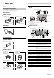
Checking the Package Contents
The following equipment and accessories are included in the package. Before
using the unit, make sure that all items are included.
Sensor Amplifier
DIN rail mount type
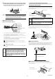
Sensor Head
List of Optional Parts
For sensor amplifier
For sensor head
Sensor amplifier x 1
Instruction manual x 1
SK-1000 (main unit)
Sensor amplifier x 1
SK-1050 (expansion unit)
Sensor head x 1
SK-050
OP-26751 (for SK-1000/1050)
End unit x 2
OP-87056 (2 m)
OP-87057 (5 m)
OP-87058 (10 m)
OP87059 (20 m)
Sensor head connection cable
(M8 straight connector) x 1
OP-87660 (2 m)
OP-87661 (5 m)
OP-87662 (10 m)
OP87663 (20 m)
Sensor head connection cable
(M8 L-shaped connector) x 1
OP-84338
Sensor head
cable connector x 2
OP-87934
Ion balance monitor unit
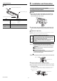
Part Names and Functions
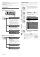
Sensor Amplifier Unit
SK-1000
*1 When shipped from the factory, a protective cover is installed over the
expansion slots.
*2 Not installed on the main unit.
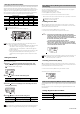
Amplifier control unit
Item Description
(1) Main display Displays the judgment value (P.V.) and each setting item.
(2) HOLD indicator
Lights up when the judgment value (P.V.) is held.
"6. Hold Function" (page 12)
(3) Judgment indicator
Displays whether the judgment value (P.V.) is HI (over the upper
limit), GO (within the acceptable range) or LO (below the lower
limit) against the tolerance setting value.
"Changing the Tolerance Values" (page 9)
(4) Bank indicator
Displays a bank in use.
"Bank Function (Registering Multiple Tolerance Setting Values)"
(page 9)
(5) Zero shift button
Press this button to match the internal measurement value (R.V.)
to zero.
(6) Sub display indicator
Lights up according to the type of values displayed on the sub
display.
(7) Sub display
Displays the internal measurement value (R.V.), temperature,
humidity, and each setting (selection) item.
(8) Timing input indicator
Lights up while the timing input is ON when the timing input
(external input) is set to Level. Lights on approx. 0.5 sec. when
the timing input is set to Edge and the timing input is turned ON.
(9) Zero shift indicator
The zero shift indicator will light up for approx. 0.5 second when
the zero shift function is used.
(10) SET button Used to perform initializations.
(11) MODE button
Used when setting items, entering/exiting setting modes or
moving items.
(12) Arrow button
Used when selecting settings, changing display contents on the
sub display, etc.
(13) Alarm indicator Lights up in the alarm state or error state.
(14)
kV display unit
indicator
Lights up when the judgment value (P.V.) display unit is kV.
(15)
V display unit
indicator
Lights up when the judgment value (P.V.) display unit is V.
HOLD
HI
V
kV
ALARM
BANK
SET MODE
SELECT
ZERO SHIFT
ZERO SHIFT
TIMING
TEMP %RH
HI LO R.V.
0
1
2
3
LO
GO
SK-1000
Expansion unit connecto
r*1
Sensor head connector
Amplifier control unit cover
Expansion unit connector
*2
Amplifier control unit
HOLD
HI
V
kV
ALARM
BANK
SET MODE
SELECT
ZERO SHIFT
ZERO SHIFT
TIMING
TEMP %RH
HI LO R.V.
0
1
2
3
LO
GO
SK-1000
(1)
(2)
(3)
(4)
(5) (6) (7) (8)
(9) (10) (11)
(12)
(13)(14)(15)