
Instruction Manual


5
E SK-1000 IM
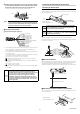
4 Install the end units (OP-26751: 2 units in a set, optional accessory)
on both sides of the amplifiers (main and expansion units). Secure
the end units in place with screws on top (2 on each end unit).
The end units are mounted in the same way as the amplifiers.
Point
Fix the amplifiers securely using the end units (OP-26751: 2 units
in a set, optional accessory) or a commercially available DIN rail
fixing tool to prevent the amplifiers from moving on the DIN rail or
coming off of the DIN rail due to machine vibration.
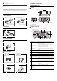
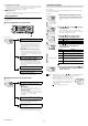
Power/Input-output cable
z "Output Circuit Diagram" (page 18)
*1 The SK-1050 (expansion unit) does not have brown, blue, or light blue wires.
Power is supplied to the expansion unit through the SK-1000 (main unit).
Use D-class grounding to ground the blue wire.
*2 The analog output (surface potential) specifications change according to the
measurement range.
The analog output can be set to one of the following values when the power is
first turned on and when initializations are performed.
None (OFF), -5 to 5 V, 0 to 5 V, 1 to 5 V, or 4 to 20 mA
" Operation When the Power is Turned on for the First Time" (page 7)
" Initial Reset (Initialize)" (page 8)
*3 In addition to the above values, you can select from the following options for
external input.
Bank B input or do not use (OFF)
" 10. External input" (page 15)
*4 When you expand the system to 6 or more units, use a power supply voltage
of 20 to 30 V.
NOTICE
• This device's 0 V power supply wire, analog output GND wire,
and grounding wire are all shared. Ensure that an electric
potential difference does not occur between their terminals due
to wiring or due to electric potential differences between
external devices. Failing to do so may lead to accidents or
breakdowns involving the external devices and this product.
• Use power supplies that are isolated from each other or so that
negative grounding is present between them. You cannot use
positive grounding.
End unit
End unit
HOLD
HI
V
kV
ALARM
BANK
SET MODE
SELECT
ZERO SHIFT
ZERO SHIFT
TIMING
TEMP %RH
HI LO R.V.
0
1
2
3
LO
GO
Brown
Blue
Black
White
Gray
Light blue
Orange
Shield
Pink
Yellow
Pink/Purple
Purple
Green
10 to 30 VDC
0 V, grounding wire
HI judgment output
LO judgment output
GO judgment output
Analog output (surface potential)
Analog output GND
Zero shift input
Reset input
Timing input
Bank A Input
Alarm output
*1
*4
*1
*1
*2
*2
*3
*3
*3
*3
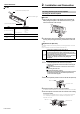
Connecting and Mounting the Sensor Head
Mounting the Sensor Head
Attach the sensor head using the dedicated mounting bracket.
When you attach the sensor head, be careful not to touch the aperture. Doing so
may lead to malfunctions.
Measurement area
The following figures briefly show the measurement area of the SK-050.
The measured value is the average of the values detected within the measurement
area as seen in the figures.
Measurement distance
The SK-050 provides a high-precision mode and a wide-range mode. Each mode
offers different measurement distances between the sensor head and the target.
The figure below shows the reference distance for measurements in each
measurement mode. The reference plane is the bottom surface of the sensor head.
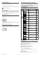
Attaching the ion balance monitor unit (OP-87934)
Fix with screws using the mounting holes in the sensor's main body and those of
the ion balance plate.
WARNING
Install the sensor unit (including its metal parts) so that nothing
touches it during measurement. Failing to do so not only prevents
proper measurements of static electricity but may also lead to
electric shock and product breakdown.
NOTICE
Do not cover the area around the temperature/humidity sensing
unit. Doing so will prevent you from correctly measuring the
ambient temperature/humidity.
Mounting holes
Sensor
unit
Tightening torque:
1.2 Nm (12kgf•cm) or less
50 mm
60 mm
100 mm
120 mm
25 mm
12 mm
5 mm
φ 200
φ 250
φ 500
φ 620
φ 80
φ 30
φ12
High-precision mode: 25 mm
Wide-range mode: 100 mm
Tightening torque:
1.2 Nm (12kgf•cm) or less