
Instruction Manual


6
E SK-1000 IM
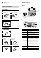
Reference
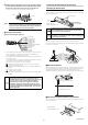
The ion balance plate can be mounted from either side of the sensor
head.
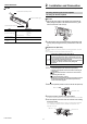
Connection and Wiring
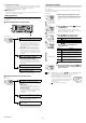
Connecting the sensor head and amplifier
1 Attach the sensor head connection cables to the sensor head cable
Point
Tighten the connectors securely by hand.
2 Attach the sensor head connection cable to the amplifier connector.
Remove the lock cover of the connector and insert it into the connectors of
amplifier until a clicking sound is heard.
3 Attach the lock cover to the connector to secure the cable.
Point
When removing the sensor head connection cable, push in the
lock lever and pull it out.
NOTICE
Be sure to fasten screws from the ion balance plate side. If
fastened from the main body side, the ion balance plate can
contact other parts, resulting in incorrect measurement.
(1) Align the arrow position of the connector to
insert.
(2) Rotate the connector screw to tighten.
Click
Lock cover
Unlocked
Lock cover
Unlocked
Lock lever
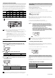
Attaching the sensor head cable connector (OP-84338:
optional accessory)
Cut the sensor head connection cable to the required length and attach the new
connector to use the sensor.
1 Cut the cable to the required length and strip approx. 15 mm of
insulation from the end of the cable.
Point
Do not strip the core wire insulation.
2 Insert the wires into the connector holes of the matching color.
The cables should be inserted to the end and held in place.
3 Confirm that all wires are inserted to the specified position and
crimp them using pliers or a similar tool.
Point
After the connector is changed, connect it to the amplifier and
confirm normal operation.
If it does not operate normally, crimp the connector again with
pliers.
Once the connector is crimped, it cannot be reused.
Blue
White
Black
Brown
Insert the
wires beyond
this point