
Instruction Manual


7
E SK-1000 IM
3. Basic Operations
This chapter describes basic operations and settings for the SK Series.
Operation When the Power is Turned on for the First Time
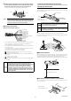
When the amplifier is turned on for the first time after the sensor head is
connected, the initial setting screen appears after a few seconds. Adjust the initial
settings according to the following procedure.
The initial setting is necessary for both the main unit and the expansion units when
they are added.
Point
Once the initial setting is completed, the initial setting display will
not appear when the power is turned on the second time or
thereafter.
To change these settings, perform an initial reset.
"Initial Reset (Initialize)" (page 8)
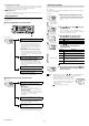
4 Change other settings as necessary.
1 Press S / T button to select the polarity of
judgment output and alarm output, and then
press [MODE] button.
[MODE] button
2 Press S / T button to select the type of
analog output and press [MODE] button.
(For SK-1000 only)
[MODE] button
3 After the setting is complete, [end] blinks
several times on the sub display and the main
screen appears.
Power ON
PRP
LASER
BANK
0
1
2
3
HI
LO
R.V.
ANALOG
HI SHIFT
ZERO SHIFT
TIMING
LO
ALIGNMENT
QWV
GO
HOLD CALC
CHECK
Output polarity
Setting value
Description
npn
NPN output
pnp
PNP output
HOLD
HI
V
kV
ALARM
BANK
ZERO SHIFT
TIMING
TEMP %RH
HI LO R.V.
0
1
2
3
LO
GO
Analog output
Setting value
Description
off
Not output
0-5u
Analog output after the judgment value (P.V.) is
converted to the range from 0 to 5 V.
-5-5u
Analog output after the judgment value (P.V.) is
converted to the range from -5 to 5 V.
1-5u
Analog output after the judgment value (P.V.) is
converted to the range from 1 to 5 V.
aMpr
Analog output after the judgment value (P.V.) is
converted to the range from 4 to 20 mA.
HOLD
HI
V
kV
ALARM
BANK
ZERO SHIFT
TIMING
TEMP %RH
HI LO R.V.
0
1
2
3
LO
GO
Operations on the Main Screens
R.V. (Internal Measurement Value) and P.V. (Judgment Value)
This section describes R.V. (Internal Measurement Value) displayed on the sub
display (lower level) and P.V. (Judgment Value) displayed on the main display
(upper level).
R.V. (Internal Measurement Value)
R.V. (Internal Measurement Value) is the value displayed when a target is inserted
into the measurement range. Only the charge potential can be displayed.
* R.V. = Raw Value
P.V. (Judgment Value)
P.V. (Judgment Value) is the value to set the judgment output to ON/OFF
according to the tolerance setting value. Also, the analog output is output based
on the P.V.. Only the charge potential can be displayed.
* P.V. = Present Value
"Changing the Tolerance Values" (page 9)
The Judgment value (P.V.) and the Internal Measurement Value (R.V.) are typically
the same value. However, when the hold function, step-count filter, or the calculation
function is used, they will become different values.
"6. Hold Function" (page 12)
* The R.V. and P.V. cannot be displayed for the temperature and humidity.
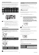
Main Display (Upper Level)
The judgment value (P.V.) is shown on the main display.
The display varies according to the functions used such as Normal, Hold function,
and the Calculation function.
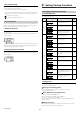
Sub Display (Lower Level)
The sub display can be switched with the arrow buttons W / X Depending on the
type of displayed value, the sub display indicator [R.V. / TEMP / %RH / HI / LO]
lights up.
(1) Temperature/humidity display screen
The temperature and humidity detected by the sensor head are displayed.
(2) Temperature display screen
The temperature detected by the sensor head is displayed.
(3) Humidity display screen
The humidity detected by the sensor head is displayed.
(4) HI side setting value screen
The upper limit of the acceptable range (tolerance setting value) for the target
is displayed. This setting value can be changed. If the judgment value (P.V.)
exceeds the value set here, the HI judgment output turns on.
"Changing the Tolerance Values" (page 9)
Normal
The same value as the internal measurement value (R.V.) is
displayed as a judgment value (P.V.).
When the hold function is used
The judgment value (P.V.) is held according to the hold
function settings.
"6. Hold Function" (page 12)
HOLD
HI
V
kV
ALARM
BANK
ZERO SHIFT
TIMING
TEMP %RH
HI LO R.V.
0
1
2
3
LO
GO
HOLD
HI
V
kV
ALARM
BANK
ZERO SHIFT
TIMING
TEMP %RH
HI LO R.V.
0
1
2
3
LO
GO
[HOLD] ON
HOLD
HI
V
kV
ALARM
BANK
ZERO SHIFT
TIMING
TEMP %RH
HI LO R.V.
0
1
2
3
LO
GO
HOLD
HI
V
kV
ALARM
BANK
ZERO SHIFT
TIMING
TEMP %RH
HI LO R.V.
0
1
2
3
LO
GO
HOLD
HI
V
kV
ALARM
BANK
ZERO SHIFT
TIMING
TEMP %RH
HI LO R.V.
0
1
2
3
LO
GO
HOLD
HI
V
kV
ALARM
BANK
ZERO SHIFT
TIMING
TEMP %RH
HI LO R.V.
0
1
2
3
LO
GO
HOLD
HI
V
kV
ALARM
BANK
ZERO SHIFT
TIMING
TEMP %RH
HI LO R.V.
0
1
2
3
LO
GO
HOLD
HI
V
kV
ALARM
BANK
ZERO SHIFT
TIMING
TEMP %RH
HI LO R.V.
0
1
2
3
LO
GO
R.V.
[
R.V.
]
ON
[
HI
]
ON
HI side setting value
LO side setting value
[
LO
]
ON
[
TEMP][
%
RH]
ON
[
TEMP
]
ON
Temperature
Temperature/Humidity
Humidity
[%
RH
]
ON
(1) Temperature/humidity display screen (6) R.V. display screen
(2) Temperature display screen (5) LO side setting value screen
(3) Humidity display screen (4) HI side setting value screen