
Instruction Manual


8
E SK-1000 IM
(5) LO side setting value screen
The lower limit of the acceptable range (tolerance setting value) for the target
is displayed. This setting value can be changed. If the judgment value (P.V.)
falls below the value set here, the LO judgment output turns on.
"Changing the Tolerance Values" (page 9)
(6) R.V. display screen
The internal measurement value (R.V.) is displayed. The displayed value is not
held even if a hold function is enabled.
Setting Operations
This section explains the functions of the main screen and the functions of each
setting screen.
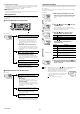
Functions Operable on the Main Screen
Available Functions from the Main Screen
Main screen
Press W or X button.
Switching the sub display (lower level; page
7)
The internal measurement value (R.V.), HI
side setting value, LO side setting value,
temperature and humidity, temperature, or
humidity is displayed, and the settings can
be changed.
"Changing the Tolerance Values" (page 9)
Set the HI side tolerance setting value and
the LO side tolerance setting value. The value
is judged as HI, GO, or LO and is displayed
and output.
While pressing down [MODE], press
S
or
T
button.
"Bank Function (Registering Multiple
Tolerance Setting Values)" (page 9)
The HI side setting value, LO side setting
value, and shift target value can be saved in
up to four different banks, and the bank can
be switched.
Press [MODE] and
S
buttons for approx. 2 seconds.
or
Press [MODE] and
S
buttons for approx. 2 seconds.
"Key Lock Function" (page 10)
This function prevents unwanted button
operations during measurement.
Main screen
Press [MODE] button for approx. 2 seconds.
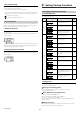
"Basic Settings and Advanced Settings"
(page 10)
Basic settings
Configure basic settings such as the
measurement mode and the averaging rate.
Advanced settings
Configure more advanced settings such as
the hold function and the timing input in order
to use the unit in a wider range of
applications.
While pressing the [MODE] button, press the
[SET] button 5 times.
"Initial Reset (Initialize)" (page 8)
All settings, excluding the calibration
function, are initialized.
[While pressing the [MODE] button, press the
W button 5 times.
"Simulation Mode" (page 17)
You can use this function to check that the I/O
wires for control have been wired correctly.
HOLD
HI
V
kV
ALARM
BANK
SET MODE
SELECT
ZERO SHIFT
ZERO SHIFT
TIMING
TEMP %RH
HI LO R.V.
0
1
2
3
LO
GO
SK-1000
Buttons used
HOLD
HI
V
kV
ALARM
BANK
ZERO SHIFT
TIMING
TEMP %RH
HI LO R.V.
0
1
2
3
LO
GO
HOLD
HI
V
kV
ALARM
BANK
ZERO SHIFT
TIMING
TEMP %RH
HI LO R.V.
0
1
2
3
LO
GO
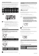
Initial Reset (Initialize)
When an initial reset is performed, all settings, excluding the calibration function,
are initialized.
The judgment output's polarity and analog output setting can also be changed
through the same operation.
Reference
• When buttons other than the S / T button and [MODE] button are
pressed during the initial reset procedure, the initial reset is
canceled and the screen in step 2 is restored.
• When you attempt to initialize the unit while
the key lock function is set, the screen shown
on the right appears and the initialization fails.
Cancel the key lock before attempting to
initialize the unit.
"Key Lock Function" (page 10)
Main screen
1 While pressing the [MODE] button on the
main screen, press the [SET] button 5 times.
[reset] is displayed on the main display (upper
level).
While pressing
the [MODE]
button, press the
[SET] button 5
times.
2 Press S / T button to select [yes] and press
the [MODE] button.
If [no] is selected at this point, only the output
polarity and analog output settings can be changed
without performing the initial reset.
[MODE] button
3 Press S / T button to select the output
polarity and press the [MODE] button.
[MODE] button
4 Press S / T button to select the analog
output and press the [MODE] button.
(For SK-1000 only)
"9. Analog output scaling" (page 14)
[MODE] button
5 After the initialization is complete, [end] blinks
several times on the sub display and the main
screen is restored.
HOLD
HI
V
kV
ALARM
BANK
ZERO SHIFT
TIMING
TEMP %RH
HI LO R.V.
0
1
2
3
LO
GO
HOLD
HI
V
kV
ALARM
BANK
ZERO SHIFT
TIMING
TEMP %RH
HI LO R.V.
0
1
2
3
LO
GO
Performing the initial reset
PRP
LASER
BANK
0
1
2
3
HI
LO
R.V.
ANALOG
HI SHIFT
ZERO SHIFT
TIMING
LO
ALIGNMENT
QWV
GO
HOLD CALC
CHECK
Output polarity
Setting value
Description
npn
NPN output
pnp
PNP output
HOLD
HI
V
kV
ALARM
BANK
ZERO SHIFT
TIMING
TEMP %RH
HI LO R.V.
0
1
2
3
LO
GO
Analog output
Setting value
Description
off
Not output
0-5u
Analog output after the judgment value (P.V.) is
converted to the range from 0 to 5 V.
-5-5u
Analog output after the judgment value (P.V.) is
converted to the range from -5 to 5 V.
1-5u
Analog output after the judgment value (P.V.) is
converted to the range from 1 to 5 V.
aMpr
Analog output after the judgment value (P.V.) is
converted to the range from 4 to 20 mA.
HOLD
HI
V
kV
ALARM
BANK
ZERO SHIFT
TIMING
TEMP %RH
HI LO R.V.
0
1
2
3
LO
GO
HOLD
HI
V
kV
ALARM
BANK
ZERO SHIFT
TIMING
TEMP %RH
HI LO R.V.
0
1
2
3
LO
GO