
Instruction Manual


9
E SK-1000 IM
Changing the Tolerance Values
The tolerance values consist of the upper limit value (HI side setting value) and the
lower limit value (LO side setting value). By setting these values, judgments are
made in three levels: when the judgment value (P.V.) goes beyond the upper limit (HI
judgment), when the judgment goes beyond the lower limit (LO judgment) and
when the judgment is within the acceptable range (GO judgment). Subsequently,
the corresponding indicator and judgment output will be turned ON/OFF.
*1 When the state of judgment output is Normally Open (default value) ON/OFF
is reversed when the state is Normally Closed.
*2 "3. Output state" (page 11)
*3 "Error Displays and Corrective Actions" (page 20)
Reference
When the setting "HI side setting value < LO side setting value" is
chosen, the judgment output is as follows.
• GO judgment output is not output regardless of the judgment value
(P.V.). (When "HI side setting value = LO side setting value =
judgment value (P.V.)" and hysteresis = 0.000, the GO judgment
output is turned on.)
• When the judgment value (P.V.) simultaneously exceeds the HI side
setting value and falls below the LO side setting value, the HI
judgment output and LO judgment output are output at the same
time.
Setting the tolerance
This is the method to directly enter the tolerance setting value (HI side setting
value, LO side setting value).
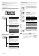
1 Press the W / X button several times on the main screen. Then
display the HI side setting value on the sub display (lower level).
"Sub Display (Lower Level)" (page 7)
2 Press S / T button to set the HI side setting value.
3
Press the
X
button once and display the LO side setting value on the
sub
display (lower level).
4 Press S / T button to set the LO side setting value.
After setting, press W / X button to return the sub display to the original
display as necessary.
Reference
As soon as the HI side setting value and the LO side setting value are
entered, the judgment and output begin with the new setting value.
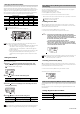
Judgment
Judgment output
*1
Judgment indicator
*2
HI GO LO HI GO LO
HI ON OFF OFF Red OFF OFF
GO OFF ON OFF OFF Green OFF
LO OFF OFF ON OFF OFF Red
Error
*3
ON OFF ON Red OFF Red
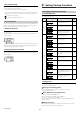
Item Setting range Default value
HI side setting value -99.999 to 99.999 1.000
Item Setting range Default value
LO side setting value -99.999 to 99.999 -1.000
HOLD
HI
V
kV
ALARM
BANK
SET MODE
SELECT
ZERO SHIFT
ZERO SHIFT
TIMING
TEMP %RH
HI LO R.V.
0
1
2
3
LO
GO
SK-1000
Judgment indicator
HOLD
HI
V
kV
ALARM
BANK
ZERO SHIFT
TIMING
TEMP %RH
HI LO R.V.
0
1
2
3
LO
GO
[LO]
ON
HI side setting value
HOLD
HI
V
kV
ALARM
BANK
ZERO SHIFT
TIMING
TEMP %RH
HI LO R.V.
0
1
2
3
LO
GO
LO side setting value
[LO]
ON
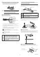
Zero Shift Function (Shifting the Internal Measurement
Value (R.V.))
The internal measurement value (R.V.) is shifted (offset) to zero. The judgment
value (P.V.) is shifted (offset) as well.
The following two methods can be used.
• Press the [ZERO SHIFT] button (<1 second).
• Set the external input (zero shift input) to ON for 20 ms or more.*
* When the zero shift input is set for the external input 1 (pink wire), the zero shift
is enabled when the input is triggered.
"10. External input" (page 15)
Enabling the Zero Shift
When the following operation is performed on the main screen, the zero shift
indicator [ZERO SHIFT] lights up for approx. 0.5 second and the current internal
measurement value (R.V.) shifts to zero.
• Press the zero shift button [ZERO SHIFT] (<1 second).
• Turn ON the zero shift input of external input for 20 ms or more.
Point
• If the power is turned OFF after a zero shift is performed by
external input, the previous state before the zero shift function is
restored. If you wish to keep the shifted state of the internal
measurement value (R.V.) even after the power is turned OFF, set
the zero shift value memory function to ON.
"12. Zero shift value memory function" (page 16)
• When the internal measurement value (R.V.) is [-----], [FFFF], or
[-FFFF] - that is, when the value is too large (a value outside of
±500 V in near mode and a value outside of ±12.5 kV in far mode)
- the zero shift function cannot be used.
Reference
When the zero shift is performed by pressing the zero shift button, the
shifted state of the internal measurement value (R.V.) is preserved
even after the power is turned off.
Canceling the Zero Shift (Reset)
When the following operation is performed on the main screen, the zero shift is
canceled and the internal measurement value (R.V.) returns to the previous state
(initial state) before the zero shift function is used.
• Press the zero shift button [ZERO SHIFT] for 2 seconds or more.
The following screen appears after operation.
Bank Function (Registering Multiple Tolerance Setting Values)
Using the bank function, you can register up to four patterns of specified tolerance
settings.
By using the bank function, multiple setting items registered beforehand can be
switched easily.
Settings Registered with each Bank
Settings Reference page
HI side setting value
"Changing the Tolerance Values" (page 9)
LO side setting value
HOLD
HI
V
kV
ALARM
BANK
ZERO SHIFT
TIMING
TEMP %RH
HI LO R.V.
0
1
2
3
LO
GO
HOLD
HI
V
kV
ALARM
BANK
ZERO SHIFT
TIMING
TEMP %RH
HI LO R.V.
0
1
2
3
LO
GO