
User guide


5
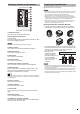
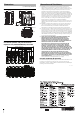
Connecting the 24 VDC Power Source
Supply 24 VDC to terminal number 7 and 8 of the IN connector.
• Use a torque of 0.25 Nm or less to tighten the screws.
• Use the electrical wires AWG14 to AWG22.
• Do not solder-coat the end of the wire. Doing so may cause fire or product
malfunction.
• Make sure to connect the frame ground terminal for the 24 VDC power
source to a type D ground.
1 After stripping the insulating
sheath by about 7 mm, insert the
lead wires into terminal No. 7 (24
VDC) and No. 8 (0 V), and then
insert the I/O terminal block into the
I/O connector as far as it can go.
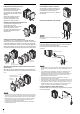
2 Connect the ground wire to the
ground port.
• Ground each device separately.
• Use a D type ground.
• Keep ground resistance under 100 Ω.
• Keep the ground wire as short as
possible.
• If it is not possible to ground each device
separately, ground them together. However, make sure that the
electrical cables are the same as shown below.
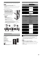
• Solderless contact sizes are listed below. M4 screws should be used.
• Tighten the screws with a torque of 0.8 [Nm].
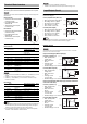
Connector Specifications
The following values show the parallel I/O connector specifications
for the system.
Connector
FX2B-40SA-1.27R
(Hirose Electric)
Color flat cable
UL20028-FRX-CF-40
(Fujikura, equivalent wire gauge
AWG28)
In normal situations, use the specialized parallel connection cable (3 m)
OP-51657 (sold separately).
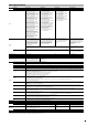
Parallel I/O Assignment: When Using Cable OP-51657
(Sold Separately)
*1 Initial assignment status is a status that system variables are assigned to
the each terminal by the initial environment settings value. This may be
different from the original description due to setting change.
*2 For more details on the each variable function, see the "List of System
Variables" of XG VisionEditor reference manual.
• COMOUT2 for Pin 17 and Pin 40 are common.
• Power source 0 V and COMIN1, COMIN2, COMOUT1, COMOUT2,
COMOUT_F+, and COMOUT_F- are all isolated.
• COMIN2 is a common terminal for input to the controller, via the parallel I/O
terminals.
• COMOUT2 is a common terminal for output from the controller, via the
parallel I/O terminals.
Parallel I/O Interface
Note
Connect the ground wire
Note
8.5 mm or
smaller
Circular connector
D-type ground* (third ground)
(ground resistance 100 Ω)
A = B
D-type ground* (third ground)
(ground resistance 100 Ω)
A > B
A < B
Device
Peripheral
Device
Peripheral
A
B
Device
Peripheral
A
B
8.5 mm or smaller
Y connector
Reference
No.
Terminal
name
Reference
Initial assignment status
*1
Circuit
diagram
Color
Variable function
*2
Bit
1 COMIN2
Common for Parallel
Inputs
––BBrown
2IN0Input 0
Custom command
parameter input
0B Red
3IN1Input 1 1 BOrange
4 IN2 Input 2 2 B Yellow
5IN3Input 3 3 BGreen
6IN4Input 4 4 B Blue
7 IN5 Input 5 5 B Purple
8IN6Input 6 6 B Gray
9 IN7 Input 7 7 B White
10 IN8 Input 8
Custom command
No. input
0BBlack
11 IN9 Input 9 1 B Brown
12 IN10 Input 10 2 B Red
13 IN11 Input 11 3 B Orange
14 IN12 Input 12
Custom command
execution input
(terminal)
0 B Yellow
15 IN13 Input 13 Reset input 0 B Green
16 IN14 Input 14
Output data switch
input
0B Blue
17 COMOUT2
Common for Parallel
Outputs (1 of 2)
– – – Purple
18 OUT0 Output 0
Handshaking
success output
0D Gray
19 OUT1 Output 1
Handshaking failure
output
0DWhite
20 OUT2 Output 2 BUSY output 0 D Black
21 OUT3 Output 3
Custom command
ready output
0DBrown
22 OUT4 Output 4
Trigger 1 ready
output
0D Red
23 OUT5 Output 5
Trigger 2 ready
output
0 D Orange
24 OUT6 Output 6
System variables
%OutDataA data
output
0 D Yellow
25 OUT7 Output 7 1 D Green
26 OUT8 Output 8 2 D Blue
27 OUT9 Output 9 3 D Purple
28 OUT10 Output 10 4 D Gray
29 OUT11 Output 11 5 D White
30 OUT12 Output 12 6 D Black
31 OUT13 Output 13 7 D Brown
32 OUT14 Output 14 8 D Red
33 OUT15 Output 15 9 D Orange
34 OUT16 Output 16 10 D Yellow
35 OUT17 Output 17 11 D Green
36 OUT18 Output 18 12 D Blue
37 OUT19 Output 19 13 D Purple
38 OUT20 Output 20 14 D Gray
39 OUT21 Output 21 15 D White
40 COMOUT2
Common for Parallel
Outputs (2 of 2)
–––Black
Reference
Note