O W N E R ’ S ST-1000 H G OME YM Questions? Call our toll free Keys Fitness Helpline 1-800-683-1236 M A N U A L
THANK YOU for making this Strength Trainer unit a part of your exercise program. Keys Fitness and our Strength Trainer Series assures the very best in value, appearance, durability and biomechanics. This manual will guide you through the assembly process. If at any time you are having trouble with the assembly or use of this product, then please contact us at our Keys Fitness Helpline. We have trained service technicians on site to take care of you, our valued customer.
BEFORE YOU START Prior to assembly, remove components from the box and verify that all the listed parts were supplied. SAFETY INFORMATION WARNING! Before using this unit or starting any exercise program, consult your physician. This is especially important for persons over the age of 35 and/or persons with pre-existing health problems. Keys Fitness Products LP assumes no responsibility for personal injury or property damage sustained by or through the use of this product.
PARTS Y
PARTS Z
PARTS [
PARTS \
PARTS LIST # 1 2 3 4 5 6 7 8 9 10 11 12 13 15 16 17 18 19 20 21 22 23 24 25 26 27 28 29 30 31 32 33 34 35 36 37 38 39 41 42 43 44 45 DESCRIPTION Base Frame Foot Plate Main Upright Rear Cross Beam Rear Top Beam Main Top Beam Foot Plate Bracket Lat Pull Down Bar Seat Pad Support Receptacle Leg Extension Lever Back Pad Support Press Arm Support Press Arm Rear Upright Front Cross Link Beam L-Pin (Long) Seat Pad Support Leg Press Main Frame Bushing (Long) Foam Tubing Foam Tubing Knee Hold Down Bar Guide Rod Wei
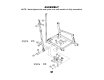
ASSEMBLY NOTE: Hand tighten bolts and nylon nuts until machine is fully assembled. Do not use bolt here yet. Wait for STEP 6. Do not use bolt here yet. Wait for STEP 6.
ASSEMBLY NOTE: Hand tighten bolts and nylon nuts until machine is fully assembled.
ASSEMBLY NOTE: Hand tighten bolts and nylon nuts until machine is fully assembled.
ASSEMBLY NOTE: Hand tighten bolts and nylon nuts until machine is fully assembled. Feed Cable (63) through framework as pictured. Hold cable in place by placing in pulley grooves and bolting pulleys to frame.
ASSEMBLY NOTE: Hand tighten bolts and nylon nuts until machine is fully assembled. First, insert guide rods into rear cross beam (4). Then slide on, from top to bottom, rubber bushings (125), 19 weight plates (128) and weight plate assembly (50). Secure in place as pictured.
ASSEMBLY NOTE: Hand tighten bolts and nylon nuts until machine is fully assembled.
ASSEMBLY NOTE: Hand tighten bolts and nylon nuts until machine is fully assembled.
ASSEMBLY NOTE: Hand tighten bolts and nylon nuts until machine is fully assembled.
ASSEMBLY NOTE: Hand tighten bolts and nylon nuts until machine is fully assembled. Hex Screws (109) are already pre-assembled for you. Make sure to unscrew them before sliding in shafts (43).
ASSEMBLY NOTE: Hand tighten bolts and nylon nuts until machine is fully assembled. Note: Hex screws (109) are already pre-assembled for you. Make sure to uncrew them before sliding in shaft(39).
ASSEMBLY NOTE: Hand tighten bolts and nylon nuts until machine is fully assembled. Note: Hex screws are already pre-assembled for you. Make sure to unscrew them before sliding in shaft (39).
ASSEMBLY NOTE: Hand tighten bolts and nylon nuts until machine is fully assembled.
ASSEMBLY NOTE: Hand tighten bolts and nylon nuts until machine is fully assembled.
ASSEMBLY NOTE: Hand tighten bolts and nylon nuts until machine is fully assembled.
ASSEMBLY NOTE: Hand tighten bolts and nylon nuts until machine is fully assembled.
ASSEMBLY NOTE: Hand tighten bolts and nylon nuts until machine is fully assembled.
ASSEMBLY NOTE: Hand tighten bolts and nylon nuts until machine is fully assembled. STEP 24 Feed cable (62) through framework as pictured. Hold cable in place by setting in pulley grooves and bolting pulleys to frame or as pictured. View finished assembly of this step in future steps or on cover page for guidance.
ASSEMBLY NOTE: Hand tighten bolts and nylon nuts until machine is fully assembled. Feed remaining section of cable (63) through leg press framework. Hold cable in place by setting in pulley grooves and bolting pulleys to frame.
ASSEMBLY NOTE: Hand tighten bolts and nylon nuts until machine is fully assembled. Feed cable (64) through framework. Hold cable in place by setting in pulley grooves and bolting pulleys to frame.
ASSEMBLY NOTE: Hand tighten bolts and nylon nuts until machine is fully assembled.
ASSEMBLY NOTE: Hand tighten bolts and nylon nuts until machine is fully assembled. Before securing weight stack covers (25,26): 1. Make sure to lightly lube the guide rods with the supplied lubrication. 2. Place the weight stack plate numbers on the weight plates. Start at the bottom and work your way up. Sticker “10” should be placed on the weight plate guide rod assembly (50).
EXPLODED VIEW 28
KEYS FITNESS PRODUCTS, L.P. STRENGTH TRAINER SERIES LIFETIME WARRANTY This Warranty applies in the United States and Canada to products manufactured or distributed by Keys Fitness Products, LP (“Keys”) under the KEYS brand name. The warranty period to the original purchaser is lifetime of the original purchaser.
Keys Fitness Products, L.P.