Agilent U2300A Series USB Multifunction Data Acquisition Devices Service Guide Agilent Technologies
Notices © Agilent Technologies, Inc. 2007 - 2010 Warranty No part of this manual may be reproduced in any form or by any means (including electronic storage and retrieval or translation into a foreign language) without prior agreement and written consent from Agilent Technologies, Inc. as governed by United States and international copyright laws. The material contained in this document is provided “as is,” and is subject to being changed, without notice, in future editions.
Safety Information The following general safety precautions must be observed during all phases of this instrument. Failure to comply with these precautions or with specific warnings elsewhere in this manual violates safety standards of design, manufacture, and intended use of the instrument. Agilent Technologies, Inc. assumes no liability for the customer’s failure to comply with these requirements.
General Safety Information IV WA R N I N G • Do not use the device if it is damaged.Before you use the device, inspect the case. Look for cracks or missing plastic. Do not operate the device around explosive gas, vapor or dust. • Do not apply more than the rated voltage (as marked on the device) between terminals, or between terminal and external ground. • Always use the device with the cables provided. • Observe all markings on the device before connecting to the device.
Waste Electrical and Electronic Equipment (WEEE) Directive 2002/96/EC This instrument complies with the WEEE Directive (2002/96/EC) marking requirement. This affixed product label indicates that you must not discard this electrical/electronic product in domestic household waste. Product Category: With reference to the equipment types in the WEEE directive Annex 1, this instrument is classified as a “Monitoring and Control Instrument” product.
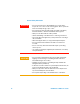
In This Guide... 1 Characteristics and Specifications 1 This chapter specifies the product specifications and electrical measurement specifications of the U2300A Series USB Multifunction DAQ devices. 2 Calibration 15 This chapter describes the step- by- step calibration procedures that covers hardware setup, self calibration, performance verification procedures and adjustment procedures.
Contents Contents 1 Characteristics and Specifications 1 Product Specifications 2 Electrical Measurement Specifications 10 2 Calibration 15 Introduction 16 Types Of Signal Sources 17 Input Configurations 18 Hardware Connection 22 Self-Calibration 26 Adjustment Procedures 32 Performance Verification Procedure 34 A/D Data Conversion 38 3 Dismantle Procedures 41 General Disassemble 42 Replacement Parts 46 4 Troubleshooting and Self-Test Procedures 47 Troubleshooting 48 Self-Test Procedures 49 A Conne
Contents Analog Output 62 VIII U2300A Series DAQ Service Guide
Agilent U2300A Series Multifunction USB DAQ Service Guide 1 Characteristics and Specifications Product Specifications 2 Electrical Measurement Specifications 10 This chapter specifies the specifications of the U2300A DAQ devices.
1 Characteristics and Specifications Product Specifications Basic Multifunction DAQ Device Specifications Table 1-1 Product specifications for basic multifunction DAQ device (U2351A, U2352A, U2353A, and U2354A) Analog Input Model Number U2351A U2352A Resolution Number of channels Maximum sampling rate Scan list memory U2353A U2354A 16 bits, no missing codes 16 SE/8 DI (software selectable/channel) 250 kSa/s 500 kSa/s Up to 100 selectable channels entries Programmable bipolar input range ±10 V,
Characteristics and Specifications Analog Output Model Number Resolution Number of channels Maximum update rate Output ranges Output coupling Output impedance Stability Power-on state Trigger sources Trigger modes FIFO buffer size Function generation mode U2351A 16 bits 2 1 MSa/s 0 to 10 V, ±10 V, 0 to AO_EXT_REF, ±AO_EXT_REF[2] DC 0.
1 Characteristics and Specifications General Purpose Digital Counter Model Number Maximum count Number of channels Compatibility Clock source Base clock available Maximum clock source frequency Input frequency range Pulse width measurement range Analog Trigger Model Number Trigger source Trigger level Trigger conditions Trigger level resolution Bandwidth Input Impedance for EXTA_TRIG Coupling Overvoltage Protection U2351A | U2352A | U2353A | U2354A (2³¹-1) bits Two independent up/down counter TTL Interna
Characteristics and Specifications General Model Number Remote interface Device class Programmable interface 1 U2351A | U2352A | U2353A | U2354A Hi-Speed USB 2.0 USBTMC Class Device Standard Commands for Programmable Instruments (SCPI) and IVI-COM [1] System Synchronous Interface (SSI) and Star-trigger commands are used when modular devices are used in instrument chassis. [2] Maximum external reference voltage for analog output (AO_EXT_REF) is ±10 V. [3] 20 minutes warm-up time is recommended.
1 Characteristics and Specifications 7.5 -7.5 Figure 1-1 Operational common mode voltage range This graph shows that the common mode voltage range is tightly linked with the output voltage. The output voltage range of the DAQ devices is ±10 V. Therefore, the common mode voltage range is ±7.5 V. Any operation beyond these voltage ranges may produce unexpected and unreliable results, and should be avoided.
Characteristics and Specifications 1 High Density Multifunction DAQ Device Specifications Table 1-2 Product specifications for high density multifunction DAQ device (U2355A, U2356A and U2331A) Analog Input Model Number Resolution Number of channels Maximum sampling rate Scan list memory Programmable bipolar input range Programmable unipolar input range Input coupling Input impedance Operational common mode voltage range Overvoltage protection Trigger sources Trigger modes FIFO buffer size Analog Output
1 Characteristics and Specifications Digital I/O Model Number Number of bits Compatibility Input voltage Input voltage range Output voltage U2355A | U2356A | U2331A 24-bit programmable input/output TTL VIL = 0.7 V max, IIL = 10 µA max VIH = 2.0 V min, IIH = 10 µA max –0.5 V to +5.5 V VOL = 0.45 V max, IOL = 8 mA max VOH = 2.
Characteristics and Specifications Digital Trigger Model Number Compatibility Response Pulse width U2355A | U2356A | U2331A TTL/CMOS Rising or falling edge 20 ns minimum Calibration[3] Model Number On board reference Temperature drift Stability U2355A | U2356A | U2331A 5V ±2 ppm/°C ±6 ppm/1000 hours General Model Number Remote interface Device class Programmable interface 1 U2355A | U2356A | U2331A Hi-Speed USB 2.
1 Characteristics and Specifications Electrical Measurement Specifications Basic Multifunction USB DAQ Device Analog Input Measurement[1] Model Number Function Offset Error Gain Error –3 dB small signal bandwidth[2] 1% THD large signal bandwidth[2] System noise CMRR U2351A | U2352A 0 °C to 18 °C 23 °C ± 5 °C 28 °C to 45 °C ±1 mV ±5 mV ±2 mV ±5 mV 760 kHz U2353A | U2354A 0°C to 18°C 23°C ± 5°C 28°C to 45°C ±1 mV ±5 mV ±2 mV ±5 mV 1.5 MHz 300 kHz 1 mVrms 300 kHz 2 mVrms 1 mVrms 2.
Characteristics and Specifications 1 [1] Specifications are for 20 minutes of warm-up time, calibration temperature at 23 °C and input range of ±10 V. [2] Specifications are based on the following test conditions.
1 Characteristics and Specifications High Density Multifunction USB DAQ Device Analog Input Measurement[1] Model Number Function Offset Error Gain Error –3 dB small signal bandwidth[2] 1% THD large signal bandwidth[2] System noise CMRR Spurious-free dynamic range (SFDR)[3] Signal-to-noise and distortion ratio (SINAD)[3] Total harmonic distortion (THD)[3] [3] Signal-to-noise ratio (SNR) Effective number of bits (ENOB)[3] Analog Output Measurement[1] Model Number Function Offset Error Gain Error Slew rate
Characteristics and Specifications 1 [1] Specifications are for 20 minutes of warm-up time, calibration temperature at 23 °C and input range of ±10 V. [2] Specifications are based on the following test conditions.
1 14 Characteristics and Specifications U2300A Series DAQ Service Guide
Agilent U2300A Series USB Multifunction DAQ Service Guide 2 Calibration Introduction 16 Types Of Signal Sources 17 Ground-referenced signal sources 17 Floating signal sources 17 Input Configurations 18 Single-ended connections 18 Differential Input Mode 20 Hardware Connection 22 Self-Calibration 26 Adjustment Procedures 32 Performance Verification Procedure 34 A/D Data Conversion 38 This chapter includes the equipments required for the calibration procedure and describe the hardware connection for analog
2 Calibration Introduction Prior to checking the performace of the instrument, ensure that you have all the equipments listed in the following to perform the verification procedure for analog input and analog output.
Calibration 2 Types Of Signal Sources Ground-referenced signal sources A ground- referenced signal source is defined as a signal source that is connected in some way to the building’s grounding system. This means that the signal source is connected to a common ground point with respect to the U2300A series DAQ (assume the host PC which is connected with DAQ is in the same power ground). Floating signal sources A floating signal source is a signal that is not connected to the building’s grounding system.
2 Calibration Input Configurations Single-ended connections A single- ended connection is applicable when the analog input signal is referenced to a ground and can be shared with other analog input signals. There are two different types of single- ended connections, which are RSE and NRSE configuration.
Calibration 2 • Non- Referenced Single- Ended (NRSE) Mode In NRSE mode, the DAQ device does not provide the grounding point. The ground reference point is provided by the external analog input signal. You can connect the signals in NRSE mode to measure ground- referenced signal sources, which are connected to the same grounding point. The following figure illustrates the connection.
2 Calibration Differential Input Mode The differential input mode provides two inputs that respond to the difference of the signal voltage. The analog input of the U2300A series DAQ has its own reference ground or signal return path. The differential mode can be used for the common- mode noise rejection if the signal source is ground- referenced. The following figure shows the connection of ground- referenced signal sources under differential input mode.
Calibration 2 The following figure illustrates the connection of a floating signal source to the U2300A series DAQ in differential input mode. For floating signal sources, additional resistor is needed at each channel to provide a bias return path. The resistor value is equivalent to about 100 times the source impedance. If the source impedance is less than 100 W, you can connect the negative polarity of the signal directly to AI_GND, as well as the negative input of the Instrumentation Amplifier.
2 Calibration Hardware Connection The connection to verify the analog input readings and analog outputs are different. To verify the analog input readings, see “Analog Input Connection” for descriptions on the way to connect the instruments. To verify the analog outputs, see “Analog Output Connection” for descriptions on hardware setup. Analog Input Connection The equipments required for analog input connection are the DAQ device, Fluke calibrator, terminal block, USB mini- B cable and SCSI cable.
Calibration DAQ AI101 ... AI164 AIGND 2 Calibrator Output GND Figure 2-5 The analog input and calibrator connection Setup diagram Terminal Block DAQ SCSI Cable Mini-B USB Cable PC Analog Input (e.g.
2 Calibration Analog Output Connection The equipments required for analog output connection are the DAQ device, DMM, terminal block, USB mini- B cable and SCSI cable. Follow the follwing step- by- step instruction for analog input connection. 1 Connect the DAQ device to a PC with a USB mini- B cable and connect the DAQ device to a U2901A terminal block using the U2901A SCSI cable. NOTE • Ensure that the PC has the DAQ device’s driver and the Agilent IO Libraries 14.2 or higher installed.
Calibration DAQ DMM AO201 Input AOGND GND 2 Figure 2-7 The analog input and DMM connection Setup diagram Terminal Block DAQ SCSI Cable Mini-B USB Cable PC Analog Output (e.g.
2 Calibration Self-Calibration Self- calibration can be operated using the following SCPI command via Agilent Connection Expert. CALibration:BEGin In calibration mode, the command will initiate a voltage adjustment in sequence for the specified Digital Analog Converter (DAC) channel. This sequence sets a zero and gain adjustment constant for each DAC output. The function of DAQ device will not carry on until the self- calibration has completed.
Calibration 2 3 Connect the DAQ device to the PC with mini- B type USB cable. The connected DAQ device will be visible in the Instrument I/O on this PC panel as illustrated in Figure 2- 5. 4 Select the DAQ device that you wish to send the SCPI commands to and then click the Interactive IO icon on the toolbar to launch the Agilent Interactive IO. See Figure 2- 5.
2 Calibration 6 Successful communication between the Agilent Connection Expert and the connected hardware will be shown in the Instrument Session History panel. The users may now send other SCPI commands to the instrument. Figure 2-10 Interactive IO dialog box 7 Ensure that the DAQ device has been warmed up for 30 minutes. Send the SCPI commands “*RST” and “*CLS” to clear the register in DAQ device. 8 Send “CAL:BEG” to start the self- calibration process. This process may take a few minutes to complete.
Calibration 2 Option 2: Self-calibration with Agilent Measurement Manager WA R N I N G • Unplug all cables that are connected to the DAQ device before performing self-calibration. • Any cables connected to the DAQ device may cause the failure of the self-calibration process. 1 Power on the DAQ device and disconnect all connections from it. Warm it up for 30 minutes to ensure that it is operating at stable condition. 2 Connect the DAQ device to the PC with mini- B type USB cable.
2 Calibration 5 Select the instrument that you would like to perform self- calibration and the Start button will be enabled. Click Start to proceed. See Figure 2- 8. 6 The calibration process will take a few minutes to be completed. Once done, the status and results of the process will be displayed as shown in Figure 2- 9.
Calibration 2 Figure 2-13 Self Calibration Form dialog box in Agilent Measurement Manaer showing the status and resultof the self-calibration process U2300A Series DAQ Service Guide 31
2 Calibration Adjustment Procedures DAQ on- board 5 V calibration If in the performance verification procedure is not accurate, adjustment procedure is required. The following flowchart shows the steps for 5 V calibration. Step 1: Open the DAQ device metal casing. Power on DAQ device and warm up for 30 minutes. Connect the DMM to U37 on the daughter board. Step 2: 5 V calibration Connect the DAQ device to the computer with USB cable. Monitor the DMM readings.
Calibration 2 Table 2-3 Step-by-step descriptions for Figure 2-10 Step Descriptions Step 1 Before power on the DAQ device, open the DAQ device’s metal casing. Refer to “Dismantle Procedures” for more information to disassemble the unit. Then, power on the DAQ device and warm it up for approximately 30 minutes. Connect the DMM to U37 on the daughter board. The following images shows the location of U37 and the way to connect it.
2 Calibration Performance Verification Procedure Prior to calibrate the instrument, check the performance of the instrument to see if any adjustment is required, “Step 2: DAQ configuration and verification test”. This is to ensure that the DAQ device gives accurate readings or outputs. The performance verification procedure for analog input and analog output are automated and are verify using the Automated Calibration software.
Calibration 2 Step 1: DAQ self- calibration Step 1: Power on DAQ device and disconnect all connections from DAQ. Warm up for 30 minutes.
2 Calibration Step 2: DAQ configuration and verification test Step 1: Power on DAQ device and connect the calibrator to DAQ. Warm up for 30 minutes.
Calibration NOTE 2 Byte ordering must use LSB first. Analog Output Step 1: Power on DAQ device and conenct the DMM to DAQ. Warm up for 30 minutes Step 2: DAQ configuration Send “SOUR:VOLT:POL Polarity,(@Channel)”, Send “SOUR:VOLT”RSRC INT,(@Channel)”, Send “SOUR:VOLT Voltage,(@Channel)” Step 3: DMM Measure the output voltage of DAQ Repeat steps above for all channels and polarities.
2 Calibration A/D Data Conversion A/D data conversion converts analog voltage into digital information. The following section illustrates the format of acquired raw data for the A/D conversion. Below is the illustrated example of the acquired raw data scan list for CH 101, CH 102, and CH 103. #800000200 Data length indicator, The next 8 bytes (0000 0200) specifying the actual data length only, not actual data.
Calibration 2 Hence, the 16 bits binary read back calculation will be as follows. LSB MSB <11100000> <00110001> = 12768 NOTE The raw data provided by U2300A series DAQ devices is in the byte order of LSB first. Bipolar: 2 × Int16 value Converted value = ⎛ --------------------------------------⎞ × Range ⎝ resolution ⎠ 2 2 × 12768 Example of converted value = ⎛ ------------------------⎞ × 10 = 3.896 V ⎝ ⎠ 16 2 Unipolar: Int16 value Converted value = ⎛ ---------------------------- + 0.
2 Calibration There are Therefore, operation. will be as unused bits in the 12- bit data format. there is a need to perform a 4- bit right shift Hence, the 12 bits binary read back calculation follows. LSB MSB <00011110> <00000011> = 798 NOTE The raw data provided by U2300A series DAQ devices is in the byte order of LSB first.
Agilent U2300A Series USB Multifunction DAQ Service Guide 3 Dismantle Procedures General Disassemble 42 Mechanical Disassemble 42 Replacement Parts 46 This chapter describes the step- by- step disassemble procedures and list the available replacement parts for U2300A Series DAQ devices, Agilent Technologies 41
3 Dismantle Procedures General Disassemble This chapter provides the step- by- step guides on how to dismantle the module and install the replacement assembly. To assemble back the module, follow the instructions in reverse order. NOTE The parts shown in the following figures are representative and may look different than what you have in your module.
Dismantle Procedures 3 Step 2: Flip the plastic casing open. Step 3: Slide the metal casing out of the plastic casing.
3 Dismantle Procedures Step 4: Unscrew all the following indicated screws from metal casing. Front metal piece Step 5: Gently pull the front metal piece out, which is attached to the carrier and measurement boards. Step 6: Unscrew all the following indicated screws from the metal casing and remove the rear metal piece.
Dismantle Procedures 3 Disassembled parts: Metal casing Rear metal casing Carrier board and measurement board Front metal casing U2300A Series DAQ Service Guide 45
3 Dismantle Procedures Replacement Parts This section provides the information of orderable replacement parts for U2300A Series DAQ devices. The parts availabled for replacement are listed in the table below with the reference part numbers and the respective part names. You can order the replacement parts from Agilent using the part number provided in the table below.
Agilent U2300A Series USB Multifunction DAQ Service Guide 4 Troubleshooting and Self-Test Procedures Troubleshooting 48 Self-Test Procedures 49 This chapter provides the information on general troubleshooting and self-test procedures.
4 Troubleshooting and Self-Test Procedures Troubleshooting This section provides suggestions for solving general problems that you may encounter with the instrument. It guides you on what to check in the following situations: 1. Power Indicator LED is not lit Verify that the ac power cord is connected to the power inlet in the DAQ device. 2. Power Indicator LED is lit but the AO/ AI Indicator LED is not lit Verify that the USB cable is connected to the PC and the USB inlet in the DAQ device. 3.
Troubleshooting and Self-Test Procedures 4 Self-Test Procedures WA R N I N G Do not connect any cables and terminal block prior to performing self-test procedures. 4 Go to Start > All Programs > Agilent IO Libraries Suite > Agilent Connection Expert to launch the Agilent Connection Expert. 5 Go to Start > All Programs > Agilent T&M Toolkit > Agilent Interactive IO to launch the Interactive I/O dialog box.
4 50 Troubleshooting and Self-Test Procedures U2300A Series DAQ Service Guide
Agilent U2300A Series USB Multifunction DAQ Service Guide A Connector Pins Configuration Pins Configuration for U2331A, U2355A and U2356A 52 Pins Configuration for U2351A, U2352A, U2353A and U2354A 53 This appendix attached the pins configuration for all the U2300A Series DAQ devices.
A Connector Pins Configuration Pins Configuration for U2331A, U2355A and U2356A The U2300A Series DAQ is equipped with 68–pin very high density cable interconnect (VHDCI) type connectors. Figure A-1 Pins Configuration of Connector 1 for U2331A, U2355A, U2356A NOTE 52 Figure A-2 Pins Configuration of Connector 2 for U2331A, U2355A, U2356A (AIH101..132) and (AIL101..132) are for differential mode connection pair.
Connector Pins Configuration A Pins Configuration for U2351A, U2352A, U2353A and U2354A Figure A-3 Pins Configuration for U2352A, U2354A NOTE U2300A Series DAQ Service Guide Figure A-4 Pins Configuration for U2351A, U2353A (AIH101..108) and (AIL101..108) are for differential mode connection pair.
A Connector Pins Configuration Table A-5 68-pin VHDCI connector pins descriptions Signal Name Direction Reference Description Ground AI_GND N/A N/A Analog input (AI) ground. All three ground references (AI_GND, AO_GND, and D_GND) are connected together on board. For 16 Channels: Input AI_GND U2351A/U2352A/U2353A/U2354A AI<101..116> Analog input channels 101~116. Each channel pair, AI(i = 101..108), can be configured either as two single-ended inputs or one differential input (marked as AIH<101..
Connector Pins Configuration U2300A Series DAQ Service Guide A 55
A 56 Connector Pins Configuration U2300A Series DAQ Service Guide
Agilent U2300A Series USB Multifunction DAQ Service Guide B Test Limits Analog Input 58 Analog Output 62 This appendix provides the test limits for analog input and analog output when performing the verification procedure.
58 0.0015 0.002 0.002 0.0015 0.002 0.002 0.001 0.001 0.001 0.001 0.001 0.001 UNIP UNIP UNIP UNIP UNIP UNIP UNIP UNIP UNIP UNIP UNIP UNIP 0 0 0 0 0 0 0 0 0 0 0 0 10 10 10 5 5 5 2.5 2.5 2.5 1.25 1.25 1.25 Analog Input U2351A, U2352A, U2353A, U2354A: Offset/ Setting Range (V) Gain Error (V) Polarity Min Max 0.001 BIP –10 10 0.002 BIP –10 10 0.002 BIP –10 10 0.001 BIP –5 5 0.002 BIP –5 5 0.002 BIP –5 5 0.001 BIP –2.5 2.5 0.0015 BIP –2.5 2.5 0.0015 BIP –2.5 2.5 0.001 BIP –1.25 1.25 0.0015 BIP –1.25 1.25 0.
U2300A Series DAQ Service Guide 0.001 0.0015 0.0015 0.001 0.0015 0.0015 0.001 0.001 0.001 0.001 0.001 0.001 UNIP UNIP UNIP UNIP UNIP UNIP UNIP UNIP UNIP UNIP UNIP UNIP Analog Input U2355A, U2356A: Offset/ Setting Gain Error (V) Polarity 0.001 BIP 0.002 BIP 0.002 BIP 0.001 BIP 0.002 BIP 0.002 BIP 0.001 BIP 0.0015 BIP 0.0015 BIP 0.001 BIP 0.0015 BIP 0.0015 BIP 0 0 0 0 0 0 0 0 0 0 0 0 10 10 10 5 5 5 2.5 2.5 2.5 1.25 1.25 1.25 Range (V) Min Max –10 10 –10 10 –10 10 –5 5 –5 5 –5 5 –2.5 2.5 –2.5 2.5 –2.5 2.
60 BIP BIP BIP BIP BIP BIP BIP BIP BIP BIP BIP BIP BIP BIP BIP BIP BIP BIP BIP BIP BIP BIP BIP BIP BIP BIP BIP 0.001 0.001 0.001 0.001 –0.2 –0.05 –0.05 –0.05 –10 –10 –10 –5 –5 –5 –2.5 –2.5 –2.5 –1.25 –1.25 –1.25 –1 –1 –1 –0.5 –0.5 –0.5 –0.25 –0.25 –0.25 –0.2 –0.2 0.2 0.05 0.05 0.05 10 10 10 5 5 5 2.5 2.5 2.5 1.25 1.25 1.25 1 1 1 0.5 0.5 0.5 0.25 0.25 0.25 0.2 0.2 Setting Range (V) Polarity Min Max 0.002 0.006 0.006 0.0015 0.004 0.004 0.0015 0.002 0.002 0.001 0.0015 0.0015 0.001 0.001 0.001 0.001 0.
0.0015 0.004 0.004 0.0015 0.002 0.002 0.001 0.0015 0.0015 0.001 0.001 0.001 0.001 0.001 0.001 0.001 0.001 0.001 0.001 0.001 0.001 0.001 0.001 0.001 0.001 0.001 0.001 Analog Input U2331A: Offset/ Gain Error (V) UNIP UNIP UNIP UNIP UNIP UNIP UNIP UNIP UNIP UNIP UNIP UNIP UNIP UNIP UNIP UNIP UNIP UNIP UNIP UNIP UNIP UNIP UNIP UNIP UNIP UNIP UNIP 0 0 0 0 0 0 0 0 0 0 0 0 0 0 0 0 0 0 0 0 0 0 0 0 0 0 0 10 10 10 5 5 5 4 4 4 2.5 2.5 2.5 2 2 2 1 1 1 0.5 0.5 0.5 0.4 0.4 0.4 0.1 0.1 0.
62 UNIP UNIP 0.001 0.002 0 0 –10 –10 –10 0 0 –10 –10 –10 BIP BIP BIP UNIP UNIP 0.0015 0.004 0.004 0.0025 0.004 0 0 –10 –10 –10 0.0000 9.9976 0.0000 9.9951 –10.0000 10 0 10 Positive FS 10 0 10 Positive FS 10 Negative FS 0.0000 9.9976 0.0000 9.9951 –10.0000 Test Point (V) Location Value 10 0 10 Positive FS 10 0 10 Positive FS 10 Negative FS Setting Range (V) Polarity Min Max UNIP UNIP 0.001 0.002 Analog Output U2331A: Offset/ Gain Error (V) BIP BIP BIP 0.001 0.004 0.004 0.0000 9.
www.agilent.