
User manual

54 U2300A Series DAQ Service Guide
A Connector Pins Configuration
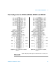
Tabl e A- 5 68-pin VHDCI connector pins descriptions
Signal Name Direction Reference
Ground
Description
AI_GND N/A N/A Analog input (AI) ground. All three ground
references (AI_GND, AO_GND, and D_GND) are
connected together on board.
For 16 Channels:
AI<101..116>
For 64 Channels:
AI<101..164>
Input AI_GND U2351A/U2352A/U2353A/U2354A
Analog input channels 101~116. Each channel pair, AI<i,
i+8>(i = 101..108), can be configured either as two
single-ended inputs or one differential input (marked as
AIH<101..108> and AIL<101..108>).
U2331A/U2356A/U2355A
Analog input channels 101~164). Each channel pair, AI<i,
i+32> (i = 101..132), is configured either as two
single-ended inputs or one differential input (marked as
AIH<101..132> and AIL<101..132>)
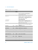
AI_SENSE Input AI_GND Analog input sense. The reference pin for any
AI<101..116> or AI<101..164> channels in NRSE input
configuration.
EXTA_TRIG Input AI_GND External AI analog trigger
AO201 Output AO_GND Analog output channel 1
AO202 Output AO_GND Analog output channel 2
AO_EXT_REF Input AO_GND External reference for AO channels
AO_GND N/A N/A Analog ground for AO
EXTD_AO_TRIG Input D_GND External AO waveform trigger
EXTD_AI_TRIG Input D_GND External AI digital trigger
RESERVED Output N/A Reserved pins. Do not connect them to any signal.
COUNT<301,302>_CLK Input D_GND Source of counter <301,302>
COUNT<301,302>_GATE Input D_GND Gate of counter <301,302>
COUNT<301,302>_OUT Input D_GND Output of counter <301,302>
COUNT<301,302>_UPDOWN Input D_GND Up/Down of counter <301,302>
EXT_TIMEBASE Input D_GND External Timebase
D_GND N/A N/A Digital ground
DIO501<7,0> PIO D_GND Programmable DIO of Channel 501
DIO502<7,0> PIO D_GND Programmable DIO of Channel 502
DIO503<4,0> PIO D_GND Programmable DIO of Channel 503
DIO504<4,0> PIO D_GND Programmable DIO of Channel 504