
User Manual
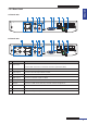
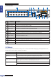
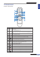
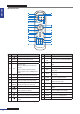
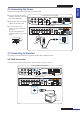
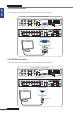
Table Of Contents
- About this Manual
- Chapter 1: Product Overview
- Chapter 2: Installation
- Chapter 3: Getting Started
- Chapter 4: Using the DVR
- Chapter 5: KGUARD Web Client
- 5.1 Login
- 5.2 The Interface
- 5.3 Live Viewing
- 5.4 Searching and Playing Recorded Videos
- 5.5 Remote Settings
- 5.6 Local Settings
- Chapter 6: Using KView Series Software
- Chapter 7: Troubleshooting & FAQ
- Appendix: Specifications
ENGLISH
Chapter 1: Product Overview
12
DVR User’s Manual
16-Channel DVR
RS-485ALARM
SENSOR
G 1234G5 678
HDMI
5
6
7
8
1
2
AUDIO
OUTPUT
1
2
3
4
13
14
15
16
9
10
11
12
VIDEO INPUT
3
4
AUDIO
INPUT
VIDEO OUTPUT
LAN
VGA
IR-EXT
12V
1 2 3 4 5
12 11 10 9 8
6 7
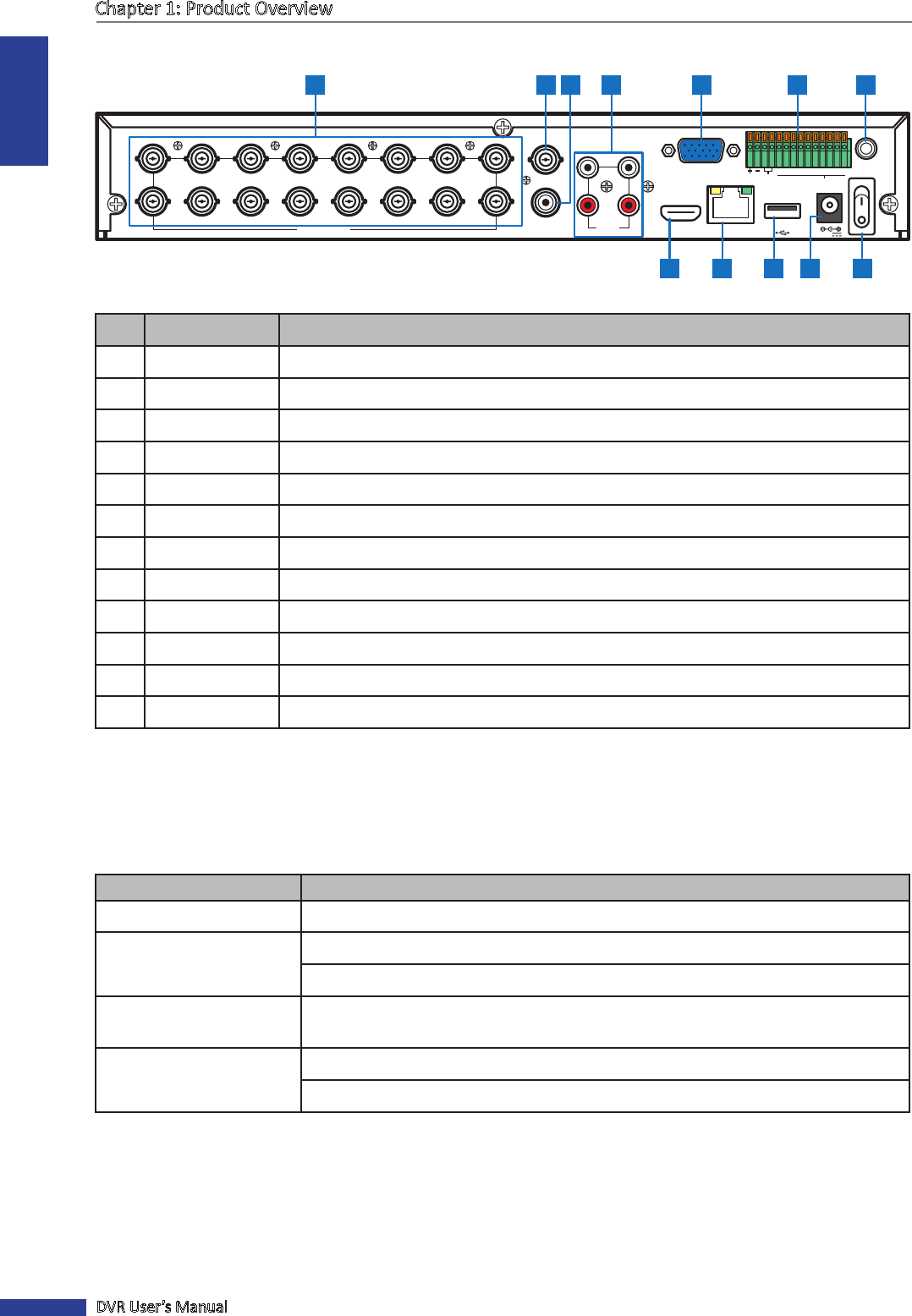
No. Connector Descripon
1 Video input Connects to a maximum of 16 video input devices via BNC.
2 Video output Connects to a video output device via BNC.
3 Audio output Connects to an audio output device via RCA.
4 Audio input Connects to a maximum of 4 audio input devices via RCA.
5 VGA output Connects to a VGA monitor.
6 RS-485 Connects to a Speed dome camera, sensor or alarm device via RS-485.
7 IR-EXT port Connects to an IR extender device.
8 Power switch Press to turn the DVR on or o.
9 Power Connects to the power adapter.
10 USB port Connects to a USB mouse, ash disk, and other external storage drive.
11 LAN Connects to LAN via RJ-45.
12 HDMI output Connects to a monitor output via HDMI.
1.4 Mouse
The DVR is supplied with a USB mouse that you can use to operate the DVR. Simply plug in the supplied mouse into
the USB mouse connector at the rear panel of the device.
Mouse Operaon Descripon
Le-click In OSD menu, click the le buon to select and edit the seng.
Right-click In preview mode, click the right buon to display the pop-up menu.
In main menu or sub menu mode, click the right buon to exit the current menu.
Double-click the Le buon Double-click the live image of any channel for full screen display. Double-click the le
buon again to return to the window-display of all cameras.
Drag an area/line In moon mode, use this funcon to select moon area.
In [Color Setup] menu mode, it will adjust color control bar.