
User Manual
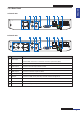
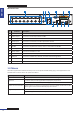
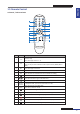
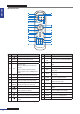
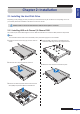
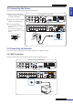
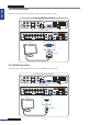
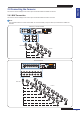
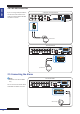
Table Of Contents
- About this Manual
- Chapter 1: Product Overview
- Chapter 2: Installation
- Chapter 3: Getting Started
- Chapter 4: Using the DVR
- Chapter 5: KGUARD Web Client
- 5.1 Login
- 5.2 The Interface
- 5.3 Live Viewing
- 5.4 Searching and Playing Recorded Videos
- 5.5 Remote Settings
- 5.6 Local Settings
- Chapter 6: Using KView Series Software
- Chapter 7: Troubleshooting & FAQ
- Appendix: Specifications
ENGLISH
Chapter 2: Installaon
DVR User’s Manual
17
2.2 Connecng the Power
Use only the supplied power adapter that came with the DVR.
1 Connect one end of the power
adapter to the power connector
on the back of the DVR.
2 Plug the other end of the power
adapter into the wall outlet.
3 For 4-channel/8-channel
models, the DVR automacally
powers on.
For a 16-channel DVR, press
the Power switch to turn on the
power.
VIDEO
INPUT
LAN
RS-485VGA
12V
CAUTION
RISK OF ELECTRIC SHOCK
DO NOT OPEN
HDMI
5
6
7
8
1
2
AUDIO
OUTPUT
1
2
3
4
VIDEO
INPUT
AUDIO
INPUT
VIDEO
OUTPUT
RS-485 ALARM
SENSOR
G1234G5678
HDMI
5
6
7
8
1
2
AUDIO
OUTPUT
1
2
3
4
13
14
15
16
9
10
11
12
VIDEO INPUT
3
4
AUDIO
INPUT
VIDEO OUTPUT
LAN
VGA
IR-EXT
12V
12V
Power adapter
Wall outlet
4-Channel DVR / 8-Channel DVR
16-Channel DVR
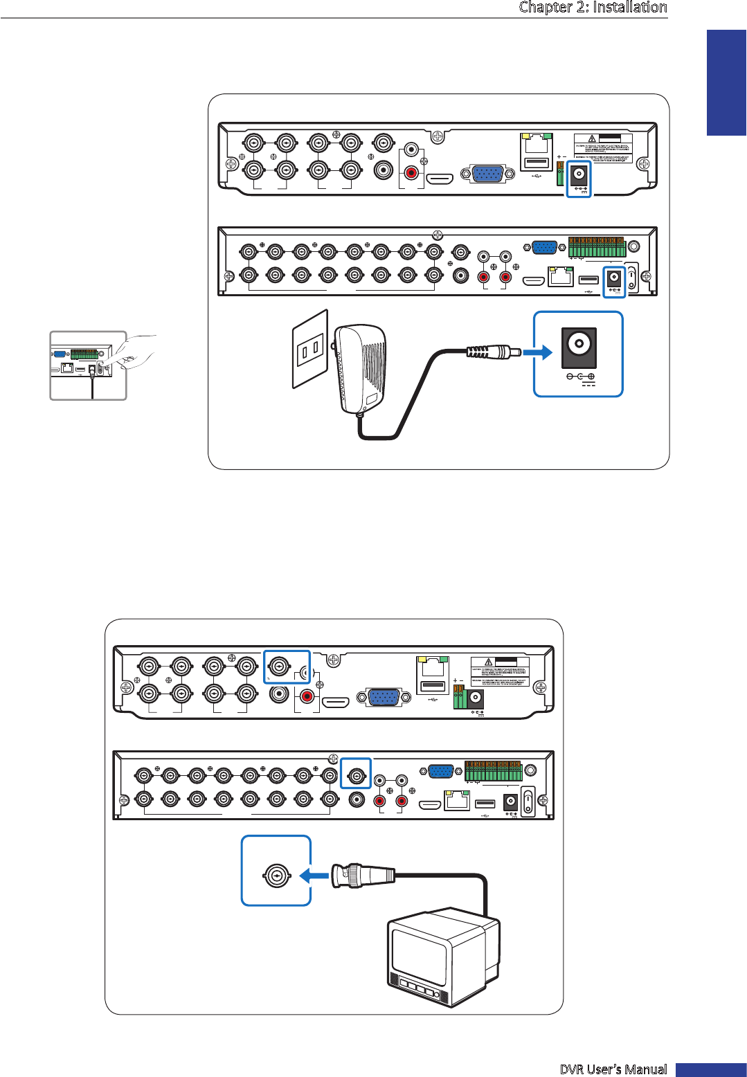
2.3 Connecng to Monitors
The preview screen can be displayed on monitors via BNC, VGA, or HDMI connecon.
2.3.1 BNC Connecon
Connect the video output of the DVR to the monitor via BNC connector as shown.
VIDEO
INPUT
LAN
RS-485VGA
12V
CAUTION
RISK OF ELECTRIC SHOCK
DO NOT OPEN
HDMI
5
6
7
8
1
2
AUDIO
OUTPUT
1
2
3
4
VIDEO
INPUT
AUDIO
INPUT
VIDEO
OUTPUT
RS-485 ALARM
SENSOR
G1234G5678
HDMI
5
6
7
8
1
2
AUDIO
OUTPUT
1
2
3
4
13
14
15
16
9
10
11
12
VIDEO INPUT
3
4
AUDIO
INPUT
VIDEO OUTPUT
LAN
VGA
IR-EXT
12V
VIDEO OUTPUT
Monitor
BNC cable
4-Channel DVR / 8-Channel DVR
16-Channel DVR
RS-485ALARM
SENSOR
G1234G5678
HDMI
LAN
VGA
IR-EXT
12V