
User Manual
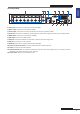
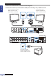
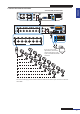

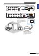
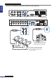
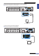
Table Of Contents
- About this Manual
- Quick Setup Guide
- Understanding the Live Viewing Screen
- Basic DVR Operation
- Accessibility Features
- Operating the DVR
- Main Menu
- Display: Live
- Display: Output
- Display: Privacy Zone
- Record: REC Para
- Record: Schedule
- Record: Record Setup
- Search: Record Search
- Search: Event Search
- Search: Log
- Network: Network
- Network: Remote Stream
- Network: Email
- Network: DDNS
- Alarm: Motion
- Device: HDD
- Device: PTZ
- Device: Cloud Storage
- System: General
- System: Users
- System: Info
- Advanced: Maintain
- Remote Access Via Web Client
- Appendix

ENGLISH
Easy Link PRO Series: Quick Setup Guide
DVR User’s Manual
17
6. Connect the alarm device via Alarm and Sensor I/O block (oponal).
NOTE: This feature is available only in 16-channel DVR.
RS-485 ALARM
SENSOR
G 1234G5678
HDMI
5
6
7
8
1
2
AUDIO
OUTPUT
1
2
3
4
13
14
15
16
9
10
11
12
VIDEO INPUT
3
4
AUDIO
INPUT
VIDEO OUTPUT
LAN
VGA
IR-EXT
12V
RS-485 ALARM
SENSOR
G1 234G5678
Alarm device (output)
Alarm out
7. Connect sensors up to 8 channels (oponal).
NOTE: This feature is available only in 16-channel DVR.
RS-485 ALARM
SENSOR
G1 234G5 678
HDMI
5
6
7
8
1
2
AUDIO
OUTPUT
1
2
3
4
13
14
15
16
9
10
11
12
VIDEO INPUT
3
4
AUDIO
INPUT
VIDEO OUTPUT
LAN
VGA
IR-EXT
12V
RS-485 ALARM
SENSOR
G 1234G5 678
Sensor device (input)
Sensor in